Accordion antenna structure with simplified construction

a technology of accordion antenna and antenna structure, which is applied in the direction of loop antennas with ferromagnetic cores, protective materials, instruments, etc., can solve the problems of antenna activation circuit, antenna sensitive at small apertures, and increasing the number of frequency bands a compact antenna can support, so as to reduce power, space/size and cost

Active Publication Date: 2018-11-15
GARMIN INT
View PDF8 Cites 17 Cited by
  • Summary
  • Abstract
  • Description
  • Claims
  • Application Information

AI Technical Summary

Benefits of technology

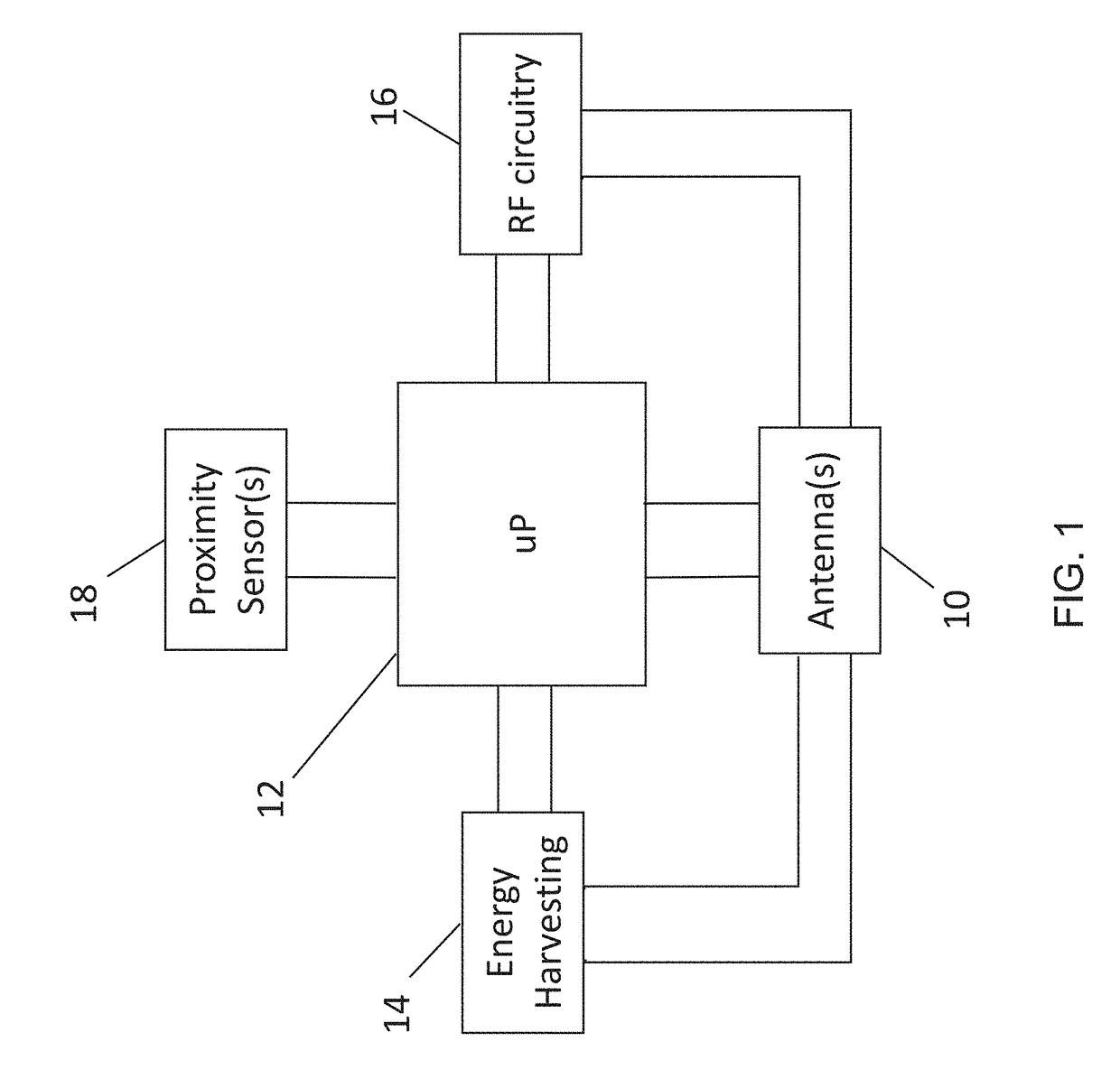
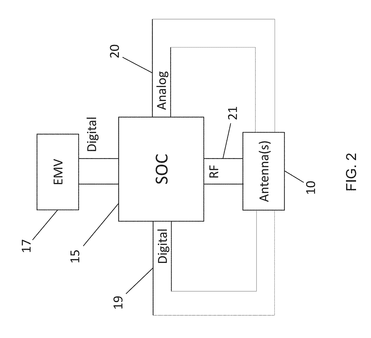
[0038]The present invention thus relates to devices, systems and methods that provide functionality using miniature, multi-purpose antenna structures, methods and systems that reduce power, space / size and cost within the constraints of powered or smart cards, and / or portable, mobile or wearable electronic devices. Moreover, the present invention provides methods and systems of remote wake-up, proximity detection, user authentication, data transfer (communications including RF (radio frequency), magnetic, electromagnetic, and / or energy transfer (energy harvesting and charging) within a multi-purpose antenna structure and / or module.

Problems solved by technology

As the antenna size is reduced, the bandwidth and number of frequency bands a compact antenna can support becomes more challenging.
Since mobile devices are typically small in size, keeping antennas sensitive at small apertures is a challenge.
An issue with these approaches is that any signal received at a resonant frequency of the antenna will activate the circuit.

Method used


Image

  • Accordion antenna structure with simplified construction
  • Accordion antenna structure with simplified construction
  • Accordion antenna structure with simplified construction

Examples


Embodiment Construction

[0113]Before describing in detail the particular methods and apparatuses related to a multi-purpose antenna for low-power close-proximity communications and energy transfer, it should be observed that the embodiments of the present invention reside primarily in a novel and non-obvious combination of elements and method steps. So as not to obscure the disclosure with details that will be readily apparent to those skilled in the art, certain conventional elements and steps have been presented with lesser detail, while the drawings and the specification describe in greater detail other elements and steps pertinent to understanding the embodiments. The presented embodiments are not intended to define limits as to the structures, elements or methods of the inventions, but only to provide exemplary constructions. The embodiments are permissive rather than mandatory and illustrative rather than exhaustive.

Overview

[0114]The disclosed invention comprises methods and systems that relate to a ...


PUM


Abstract

An antenna for generating an electromagnetic field. The antenna has a substrate and a contiguous core disposed on the substrate. A continuous winding encircles the core and the substrate extending in a longitudinal direction; a first gap is defined between adjacent turns of the winding. The turns segregated into a plurality of winding segments, each winding segment comprising a plurality of turns. A second gap is defined between adjacent winding segments, wherein the second gap is larger than the first gap. Numerical values for the various parameters of the antenna (e.g., number of turns, number of winding segments, length of the first gap, length of the second gap) are selected to create and propagate a signal having desired parameters.

Description

CROSS REFERENCE TO RELATED APPLICATIONS[0001]This patent application is a continuation-in-part of the application filed on Apr. 4, 2016, entitled Accordion Antenna Structure and assigned application Ser. No. 15 / 089,844 (Attorney Docket Number 12188-035), which claims priority to a provisional patent application entitled Miniature, Multi-Purpose Antenna Method and System for Low-Power Close-Proximity Communications and Energy Transfer and assigned application No. 62 / 143,028 (Attorney Docket Number 12188-016), both applications are incorporated herein in their entirety.FIELD OF THE INVENTION[0002]The present invention relates to the general field of miniature multi-purpose antennas, specifically antenna structures, methods and systems that support information transactions, such as payments, authentication, identification and general data exchange, that are performed between devices placed in close proximity. The devices can also perform other functions such as wake-up, communications,...

Claims


Application Information

Patent Timeline
Patent Type & Authority Applications(United States)
IPC IPC(8): H01Q1/22H01Q7/00
CPCH01Q7/00H01Q1/2225H01Q1/2291H01Q1/248H01Q1/38H01Q1/40H01Q7/08H01Q21/061H01Q21/28H04B5/0056G06Q20/321
Inventor TUNNELL, DAVIDKEEN, BRIAN
Owner GARMIN INT
Why Eureka
Try Eureka