Turbine Loads Determination and Condition Monitoring

a technology of turbine loads and condition monitoring, applied in the direction of testing/monitoring control systems, program control, instruments, etc., can solve the problems of low efficiency, blades or wings may be susceptible to excess loads,

Inactive Publication Date: 2018-11-22
FRONTIER WIND LLC
View PDF0 Cites 17 Cited by
  • Summary
  • Abstract
  • Description
  • Claims
  • Application Information

AI Technical Summary

Benefits of technology

[0003]This summary is provided to introduce a selection of concepts in a simplified form that are further described below in the Detailed Description. The Summary is no

Problems solved by technology

Excessive loads may strain the system and result in damage or lower efficiency.
In the aerodynamics field, fo

Method used


Image

  • Turbine Loads Determination and Condition Monitoring
  • Turbine Loads Determination and Condition Monitoring
  • Turbine Loads Determination and Condition Monitoring

Examples


Embodiment Construction

[0023]In the following description of various illustrative embodiments, reference is made to the accompanying drawings, which form a part hereof, and in which is shown, by way of illustration, various embodiments in which the invention may be practiced. It is to be understood that other embodiments may be utilized and structural and functional modifications may be made without departing from the scope of the present invention.

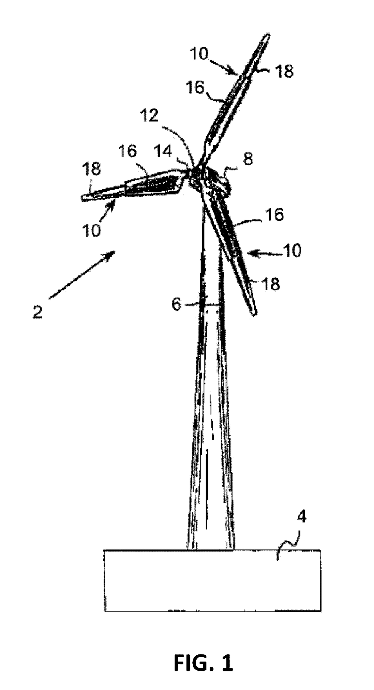
[0024]FIG. 1 illustrates a wind turbine 2 on a foundation 4 with a tower 6 supporting a nacelle 8. One or more blades 10 are attached to a hub 12 via a bolt flange 14. The hub 12 is connected to a drive train (not shown) within the nacelle 8. The blades 10 may have a root portion 16 and a tip portion 18. In one arrangement, blades 10 may be fixed length rotor blades having root portion 16 and tip portion 18. In another arrangement, the blades 10 may be variable length blades, which may be configured to extend and / or retract given certain conditions. Various mod...


PUM


Abstract

Systems and methods for determining turbine pressure related loads and for condition monitoring are provided. The systems and methods may measure at least one pressure differential on an airfoil. At least one pressure differential may be used to determine a root bending moment associated with the blade. Additionally or alternatively, at least one pressure differential may be used to determine a low-speed shaft moment for a turbine on which the blade is mounted. Still further, at least one pressure differential and/or moment may be used to gauge wear/fatigue and/or damage to one or more wind turbines. Based on this information, a controller may modify various operating characteristics of the turbine or blade to address the fatigue or damage.

Description

TECHNICAL FIELD[0001]Aspects of the present disclosure relate to determining loads and moments of blades on a wind turbine.BACKGROUND[0002]Measurement of loads in mechanical and electronic devices is often used to optimize performance. Excessive loads may strain the system and result in damage or lower efficiency. In the aerodynamics field, for example, blades or wings may be susceptible to excess loads due to the direction and magnitude of air flow. Thus, there is a need to be able to measure the loads associated with blades in an efficient, cost-effective manner.SUMMARY[0003]This summary is provided to introduce a selection of concepts in a simplified form that are further described below in the Detailed Description. The Summary is not intended to identify key features or essential features of the claimed subject matter, nor is it intended to be used to limit the scope of the claimed subject matter.[0004]Aspects described herein provide a system, apparatus, method and / or computer ...

Claims


Application Information

Patent Timeline
IPC IPC(8): F03D7/04F03D7/02G05B13/02
CPCF03D7/046F03D7/0224F03D7/0236G05B13/027F05B2240/221F05B2270/709F03D7/0204F03D7/022F05B2260/84F05B2270/324F03D17/00G05B23/0283G05B23/0286G05B2219/2619Y02E10/72
Inventor CAO, NANNANBUTTERWORTH, JEFFREY AUSTINBAKER, JONATHON PAULLIN, GUOJIANMILLER, MYRON FLOYD
Owner FRONTIER WIND LLC
Why Eureka
Try Eureka