Hydraulic control device for vehicles

a technology of hydraulic control device and vehicle, which is applied in the direction of valve operating device/release device, braking system, transportation and packaging, etc., can solve the problems of self-excited vibration, abnormal noise generation, and vehicle occupants may feel uncomfortable, so as to increase the force and increase the force pressing the valve element against the valve sea

Active Publication Date: 2018-11-29
ADVICS CO LTD
View PDF0 Cites 4 Cited by
  • Summary
  • Abstract
  • Description
  • Claims
  • Application Information

AI Technical Summary

Benefits of technology

[0023]Note that, when the change rate of the degree of opening of the retention valve is higher, the change rate of the hydraulic pressure in the fluid passage connecting the differential pressure control valve to the retention valve becomes higher. Accordingly, the relationship between the hydraulic pressure in the fluid passage and electromagnetic force generated in the differential pressure control valve largely breaks up, and the amplitude of the self-excited vibration occurring in the differential pressure control valve easily becomes larger. Unless force pressing the valve element against the valve seat is increased when the amplitude of the self-excited vibration is larger, the self-excited vibration cannot be suppressed.
[0024]In the hydraulic control device for vehicles, in

Problems solved by technology

In the brake fluid pressure control device, under the situation in which the electromagnetic valve is controlled within a range in which the valve element is not seated on the valve seat, when the brake fluid flows in the electromagnetic valve through the flow path, the valve element of the electromagnetic valve may cause self-excited vibration.
When the self-excited v

Method used


Image

  • Hydraulic control device for vehicles
  • Hydraulic control device for vehicles
  • Hydraulic control device for vehicles

Examples


Embodiment Construction

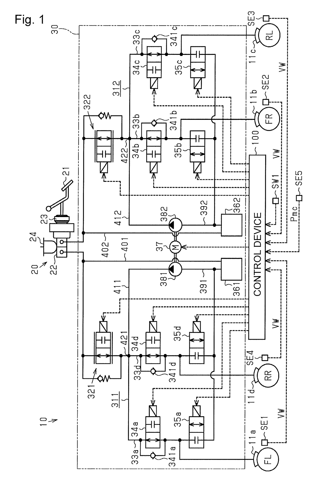
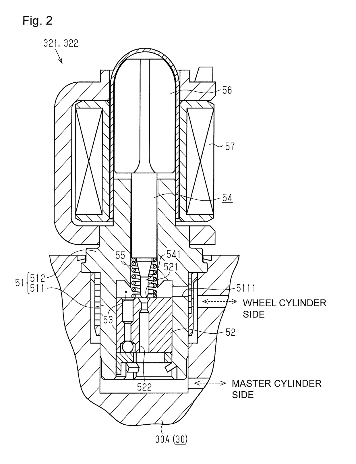
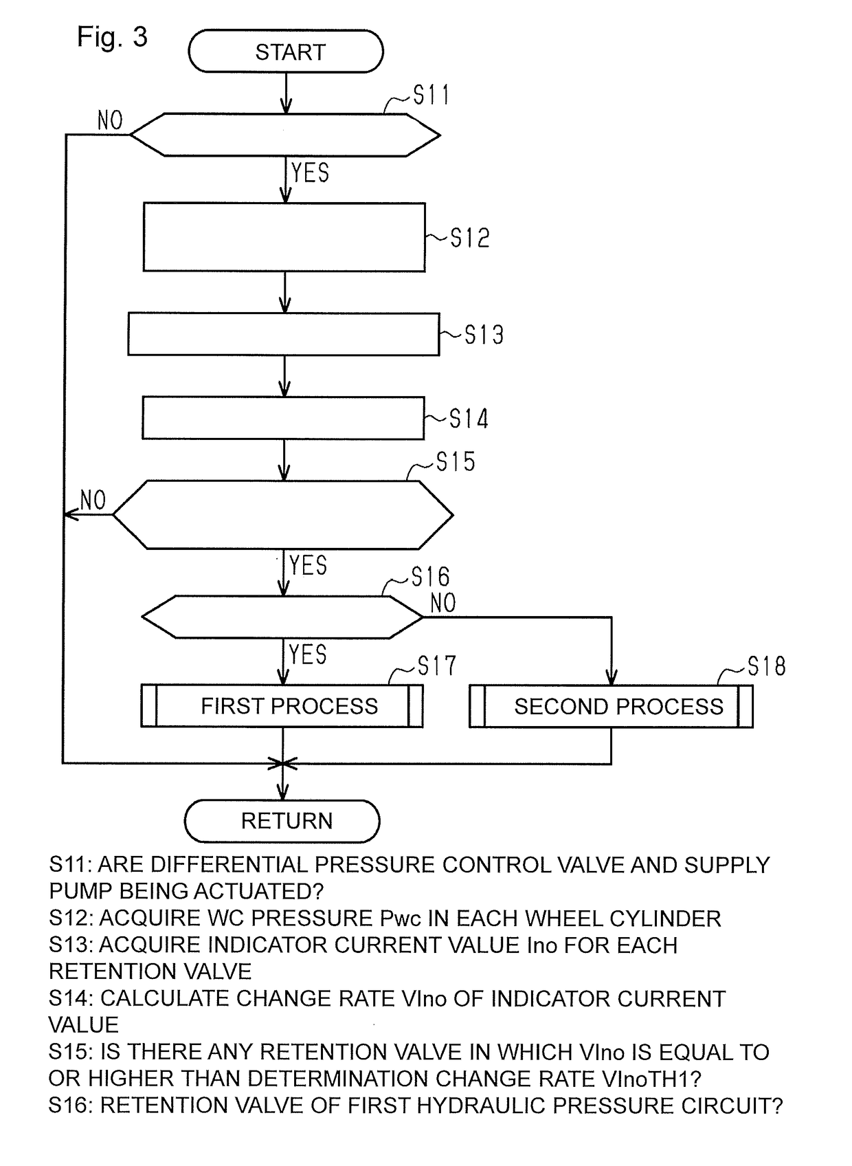
[0039]An embodiment obtained by embodying a hydraulic control device for vehicles will be described below with reference to FIGS. 1 to 9E.

[0040]As shown in FIG. 1, in a vehicle including a brake device 10 for vehicle that is a hydraulic control device for vehicles according to the present embodiment, a plurality of wheels FL, FR, RL, and RR and a plurality of wheel cylinders 11a, 11b, 11c, and 11d corresponding to wheels FL, FR, RL, and RR, respectively. The wheel cylinders 11a to 11d correspond to an example of a “control target”. A brake fluid is supplied from the brake device 10 to the wheel cylinders 11a to 11d to increase hydraulic pressures in the wheel cylinders 11a to 11d. As a result, brake forces depending on the hydraulic pressures in the wheel cylinders 11a to 11d are applied to the wheels FL, FR, RL, and RR, respectively.

[0041]The hydraulic pressures in the wheel cylinders 11a to 11d are also called “WC pressures Pwc”. The WC pressure Pwc in the wheel cylinder 11a for t...


PUM


Abstract

In the present invention, a brake device is equipped with: differential pressure control valves; pressure adjusting units which are connected to the differential pressure control valves through liquid passages; and a control device which controls the WC pressure Pwc in wheel cylinders by operating the differential pressure control valves and the pressure adjusting units. When predetermined suppression control permission conditions are satisfied while both the supply pumps of the pressure adjusting units and the differential pressure control valves are in operation, the control device performs self-excited vibration suppression control over the differential pressure control valves, the self-excited vibration suppression control being carried out in such a manner that a valve element separated from a valve seat is caused to abut on the valve seat, and, upon abutting on the valve seat, the valve element is separated from the valve seat.

Description

TECHNICAL FIELD[0001]The present invention relates a device that controls an inflow of fluid into a control target disposed in a vehicle and a hydraulic control device for vehicles including an electromagnetic valve connected to the control target through a flow path in which the fluid flows.BACKGROUND ART[0002]A brake fluid pressure control device for vehicle described in Patent Literature 1 includes a wheel cylinder serving as an example of a control target disposed on a wheel, an electromagnetic valve connected to the wheel cylinder through a flow path in which a brake fluid flows, and a control unit controlling a degree of opening of the electromagnetic valve by PWM control. The “PWM” is an abbreviation of “Pulse Width Modulation”.[0003]Note that the electromagnetic valve has a valve seat, a valve element that can reciprocally move in a direction approaching the valve seat and in a direction away from the valve seat, a solenoid in which a current having a magnitude depending on ...

Claims


Application Information

Patent Timeline
IPC IPC(8): B60T8/173B60T13/68F16K31/06
CPCB60T8/173B60T13/686F16K31/06B60T8/00B60T8/17B60T8/34B60T13/166B60T13/662F16K31/0655B60T8/36
Inventor TAKEYA, YUSUKEHASHIMOTO, KOSUKENOHIRA, SHUN
Owner ADVICS CO LTD
Why Eureka
Try Eureka