
Vehicle system

Active Publication Date: 2018-11-29
TOYOTA JIDOSHA KK
View PDF44 Cites 28 Cited by
  • Summary
  • Abstract
  • Description
  • Claims
  • Application Information

AI Technical Summary

Benefits of technology

The present disclosure is about a system that can predict the future position of an object around a vehicle. It uses a step-wise approach to optimize the first and third programs, followed by global optimization. This allows for efficient prediction of the vehicle's future position.

Problems solved by technology

However, when the number of objects present around the vehicle or the number of their types is increased, a technical problem arises in that a calculation load for the prediction is increased.
An increase in calculation load is considered to be reduced by machine learning, but a sufficient effect may not be achieved without an appropriate learning model.
When programs are individually optimized (that is, individual optimization), optimization specialized for the function of each program can be implemented, but optimization considering the function of a system as a whole cannot be implemented.
When a plurality of programs is collectively optimized (that is, global optimization) from the beginning, there is a possibility of a significant increase in processing load needed for optimization.
Since the global optimization does not consider the function of each program, a true optimal value (that is, the best value achievable by optimization) may not be achieved, and there is a possibility that the effect of optimization is not sufficiently achieved.

Method used


Image

  • Vehicle system
  • Vehicle system
  • Vehicle system

Examples


Embodiment Construction

[0023]An embodiment according to a vehicle system of the present disclosure will be described based on the drawings.

[0024]Configuration of Vehicle

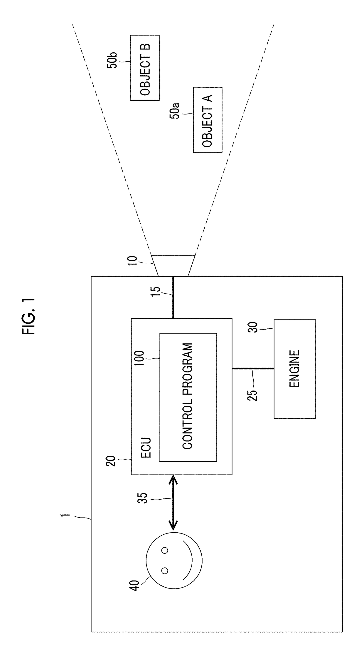
[0025]First, a configuration of a vehicle in which a vehicle system according to the embodiment is mounted will be described with reference to FIG. 1. FIG. 1 is a block diagram illustrating a configuration of a vehicle according to the embodiment.

[0026]In FIG. 1, a vehicle 1 according to the present embodiment is configured to include a sensor 10, an electrical control unit (ECU) 20, an engine 30, communication interfaces 15, 25, and a user interface 35. The ECU 20 is a specific example of an “electronic control unit”.

[0027]The sensor 10 is configured to include a vehicle-mounted camera, a radar, Laser Imaging Detection and Ranging (LIDAR), or the like and detects an object (specifically, an object A50a and an object B50b in FIG. 1) that is present around the vehicle 1. The object A 50a and the object B 50b is a specific example of an “obj...


PUM


Abstract

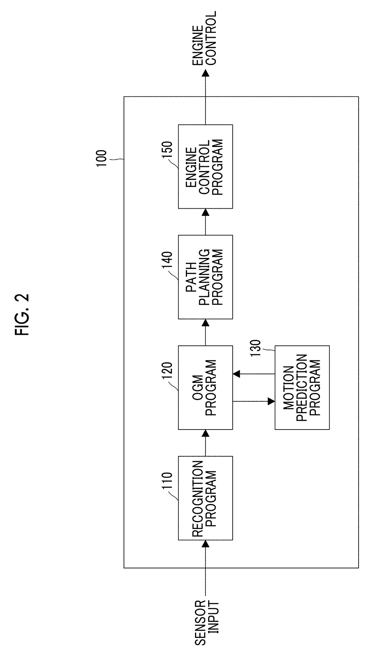
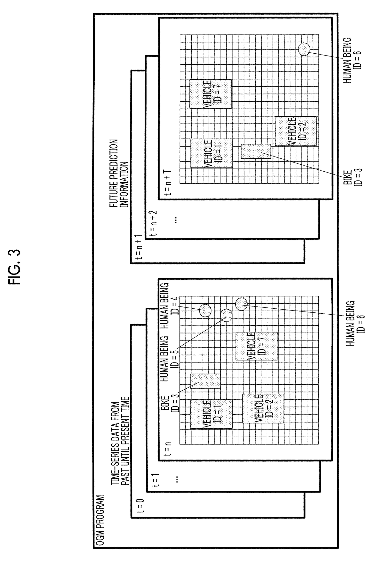
A vehicle system includes an electronic control unit. The electronic control unit is configured to execute a first program, a second program, and a third program. The first program is configured to recognize an object present around a vehicle, the second program is configured to store information related to the recognized object as time-series map data, and the third program is configured to predict a future position of the object based on the stored time-series map data. The first program and the third program are configured to be (i) first, individually optimized based on first training data corresponding to output of the first program and second training data corresponding to output of the third program, and (ii) then, collectively optimized based on the second training data corresponding to the output of the third program.

Description

CROSS-REFERENCE TO RELATED APPLICATIONS[0001]This application claims priority to Japanese Patent Application No. 2017-102634 filed on May 24, 2017, which is incorporated herein by reference in its entirety including the specification, drawings and abstract.BACKGROUND1. Technical Field[0002]The present disclosure relates to a vehicle system that predicts the motion of an object present around a vehicle.2. Description of Related Art[0003]A technology referred to as occupancy grid map (OGM) that represents a map showing a vehicle and its surrounding area on regions divided into a grid shape is known (refer to Japanese Unexamined Patent Application Publication (Translation of PCT Application) No. 2016-522508 (JP 2016-522508 A)). A technology that considers individual optimization and global optimization in an optimization problem having a plurality of evaluation functions is disclosed (refer to Japanese Unexamined Patent Application Publication No. 2002-366587 (JP 2002-366587 A)).SUMMAR...

Claims


Application Information

Patent Timeline
IPC IPC(8): B60W40/04B60W10/04B60W10/20B60W50/00G05D1/02B60W30/095G06N3/08G06N7/00
CPCB60W2050/0002G05D2201/0213B60W40/04B60W10/04B60W10/20B60W50/0097G05D1/0214G05D1/0223G05D1/0246G05D1/0257B60W30/0956G06N3/08G06N7/005B60W10/06B60W10/08B60W2400/00B60W2420/42B60W2420/52B60W2600/00B60W2710/0666B60W2710/20B60W2750/30G05D1/0088G05D1/0212B60W2050/0083B60W40/10B60W60/0027B60W2554/402G06N3/044B60W2556/00B60W2754/10G06N7/01B60W2420/403B60W2420/408
Inventor HASHIMOTO, DAISUKE
Owner TOYOTA JIDOSHA KK
Learn More