

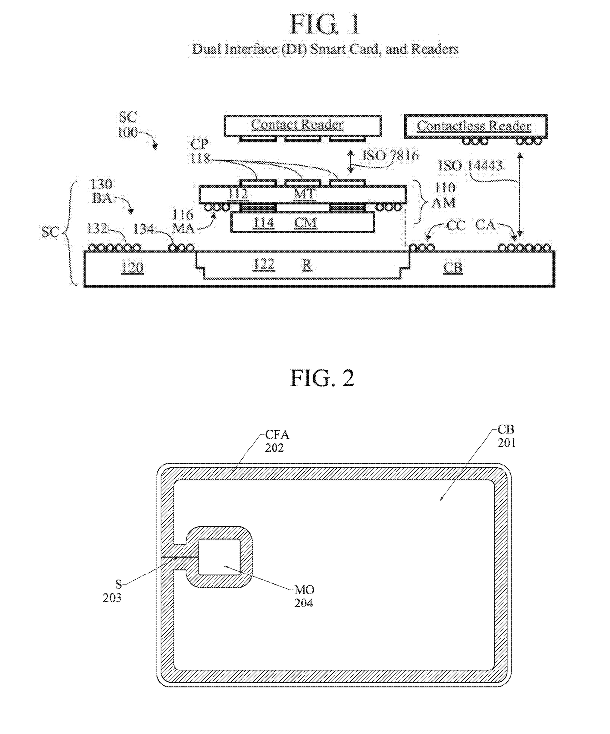
Smartcard with coupling frame antenna
a technology of coupling frame and smartcard, which is applied in the direction of antennas, antenna supports/mountings, transmission, etc., can solve the problems of reducing the effective magnetic field, reducing the power delivery to the chip, and reducing the performance of the chip, so as to improve the coupling effect of smartcard
- Summary
- Abstract
- Description
- Claims
- Application Information
AI Technical Summary
Benefits of technology
Problems solved by technology
Method used
Image

Examples
Embodiment Construction
[0120]Various embodiments (or examples) may be described to illustrate teachings of the invention(s), and should be construed as illustrative rather than limiting. It should be understood that it is not intended to limit the invention(s) to these particular embodiments. It should be understood that some individual features of various embodiments may be combined in different ways than shown, with one another. Reference herein to “one embodiment”, “an embodiment”, or similar formulations, may mean that a particular feature, structure, operation, or characteristic described in connection with the embodiment is included in at least one embodiment of the present invention. Some embodiments may not be explicitly designated as such (“an embodiment”).
[0121]The embodiments and aspects thereof may be described and illustrated in conjunction with systems, devices and methods which are meant to be exemplary and illustrative, not limiting in scope. Specific configurations and details may be set ...
PUM
 Abstract
Description
Claims
Application Information