Microfluidic systems

a microfluidic and microfluidic technology, applied in the field of microfluidic systems, can solve the problems of difficult control of flow rate and timing, large external cost of the large number of traditional loc platforms still requires external large and relatively expensive pumping mechanisms to control liquid flow, etc., to achieve easy chip use and low cost production

Active Publication Date: 2018-12-06
KATHOLIEKE UNIV LEUVEN
View PDF4 Cites 12 Cited by
  • Summary
  • Abstract
  • Description
  • Claims
  • Application Information

AI Technical Summary

Benefits of technology

[0151]For seeding of microbeads in a digital assay platform, current methods rely on expensive, not user-friendly and power-dependent microfluidic platforms for liquid manipulation which are not compatible with POC application, low cost production, robustness and user-friendliness.
[01

Problems solved by technology

Adv. Mater. 2011) However, only few microfluidics platforms for POC applications, i.e. performed close to the patient without the need for a clinical lab, have been successfully commercialized to date (Alere, Quidel, Clearview, Clearblue) due to the number of challenges that arise when accommodating complex biological assays on relatively simple devices.
However, the majority of traditional LOC platforms still requires external large and relatively expensive pumping mechanisms to control the liquid flow, such as syringe pumps, electro-pneumatic or pressure-driven systems.
However, this approach is limited to permeable materials while the control over flow rate and timing is challenging.
However, the transport of analytes and reagents in the paper matrix remains an important limitation since it decreases sensitivity and specificity of the tests, leading mainly to qualitative results.
Recently, the focus has shifted to the development of quantitative or semi-quantitative tests which, however, require an external reader reducing their portability.
One of the (many) field limitations is lack of reliable, easy to fabricate and inexpensive microfluidic components, such as micropumps and microfluidic valves.
Active microvalves require external, often bulky equipment or power supply (i.e. pneumatic, magnetic, electric, piezoelectric or thermal actuation mechanisms).
Micromachines 2011) these types of valves by large do not match the most rigorous requirements of microfluidic platforms intended for POC applications (Melin, et al.
Despite their wide usage, they do, however, present number of shortcoming: i) need for high precision and costly fabrication, ii) often poor robustness due to possible failure of moving parts and iii) incompatibility with different channel-based system (Au, et al.
Nevertheless, LOC devices have still some drawbacks for certain applications where external pumping mechanisms, like syringe pumps, make the device actuation complex and expensive.
First only one liquid can be flown over, this means that assays requiring multiple steps of liquid flow, e.g. sample-washing-secondary Ab, are diffult to achieve.
Many microfluidic platforms, where the sample in transported through very narrow channels, suffer from complicated and expensive fabrication and limited sample manipulation steps.
However, the EWOD platform requires large equipment, power supply and trained personnel increasing the cost, the complexity and reducing the portability and th

Method used


Image

  • Microfluidic systems
  • Microfluidic systems
  • Microfluidic systems

Examples


example 1

on of a Propulsion Pump According to the Present Invention Using Double-Sided Pressure Sensitive Adhesive and Filter Paper as Solid Sorbent

[0361]Materials and Reagents

[0362]Double-sided pressure sensitive adhesive (PSA) tape (200MP 7956MP) and adhesive transfer tape (467MP) were acquired from 3M (USA). Two different thickness of PVC transparent foils (180 μm or 300 μm) were tested. Filter papers with different pore sizes (0.22-13 μm) (413, VWR, Belgium; SSWP, RAWP, HATF, HVLP, GSTF, Merck Millipore, Belgium) were used. Poly(methyl methacrylate) (PMMA) plate, 2 mm thick, was shaped with laser cutter. A digital tabletop craft cutter (Cameo, Silhouette, USA) was used to cut all the PSA, filter paper and PVC foil elements of the microfluidic device. A digital camera (D3200, Nikon, Japan) with a zoom lens (AF-S DX Zoom-NIKKOR 18-55 mm f / 3.5-5.6G ED II, Nikon, Japan) was used to video record the experiments.

[0363]Different filter papers used are specified in Table 1.

TABLE 1Properties of t...

example 2

of an Embodiment of a Propulsion Pump Fabricated According to Example 1

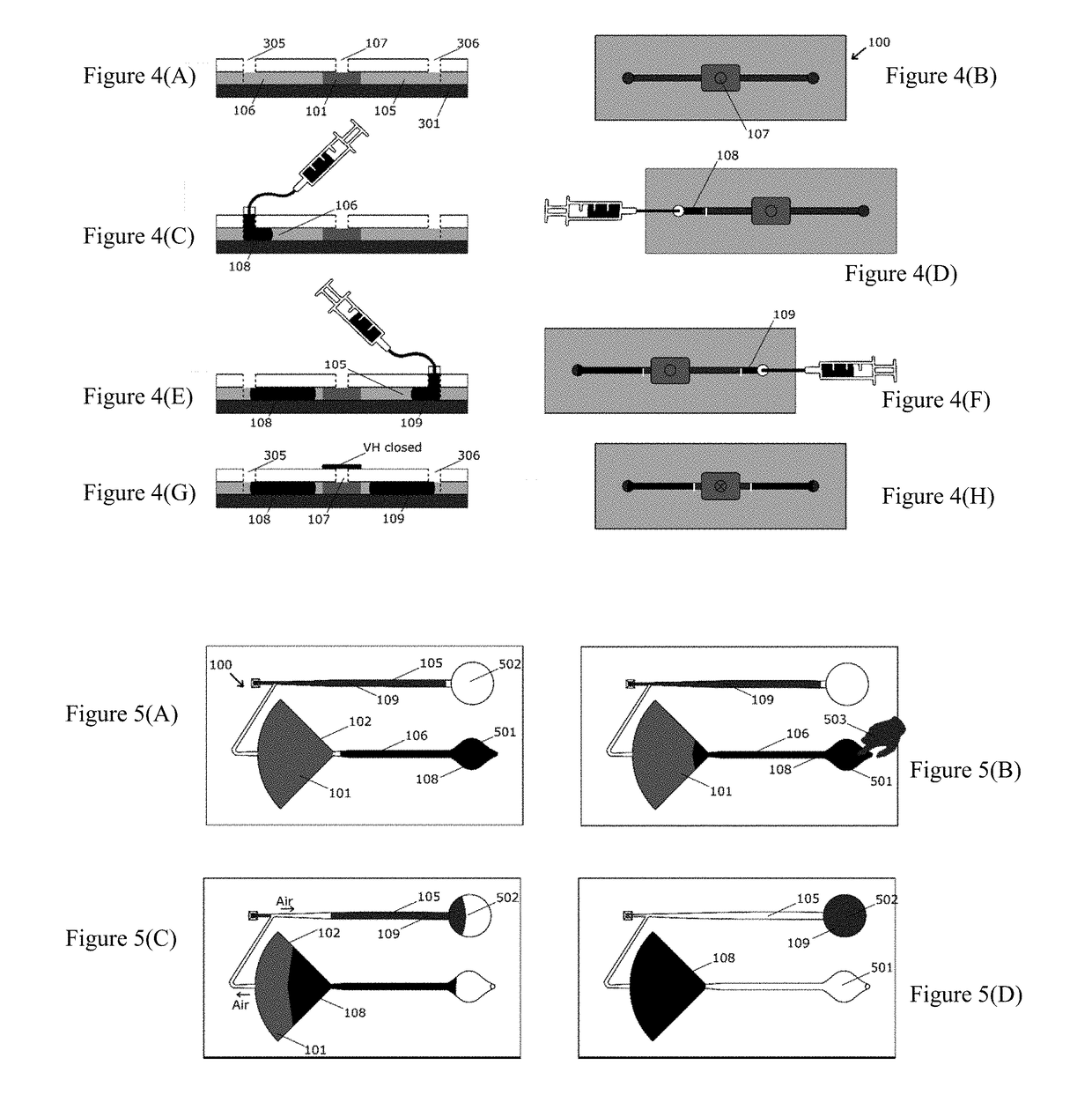
[0368]The mechanism underlying the operation of the propulsion pump according the previous examples the porous material used as solid sorbents, such as a filter paper have a given wherein the pores are filled with a gas, typically air. If the porous material is placed between the inlet and outlet of a microfluidic system, when a liquid present in the inlet side of the circuit, namely working liquid, gets in contact with the porous material, the working liquid is absorbed. At the same time, it pushes the air out of the porous material into the outlet channel. If the outlet channel is prefilled with an outlet liquid, the latter is pushed by the air towards the outlet of the microfluidic device. FIGS. 5(A) to 5(D) provide a step by step illustration of a propulsion pump according the present invention.

example 3

of the Forward Pumped Fluid in a Propulsion Pump System According to Example 2 in Relation to the Geometry and / or Pore Size of the Filter Paper

[0369]When it comes to a microfluidic system, one of the most important characteristic to take into account is the flow rate of the liquids that flow through the network. Different methods can be adopted to tune the flow rate, such as changing the channel geometry to increase or decrease the flow resistance or acting on the pumping mechanism. In the latter case for paper microfluidic solutions, it means to change paper type, shape and size. Although any water absorbing porous material could be used in the iSIMPLE concept, we selected a laboratory filter paper since its properties are well defined, it is easy to cut and it is compatible with our fabrication method.

[0370]To test this, the device was designed and prepared as described above with the overall size of the device being slightly bigger than a standard microscopy slide (35×80 mm). The...


PUM


Abstract

The present invention relates to a fluid conduit system and manufacture thereof, for the propulsion of fluids. The micro- or millifluidic system is useful within LOC, POC diagnostics digital ELISA, drug delivery applications or sampling. The system includes a capillary pump and a fluid conduit operationally connected to the pump, and a gas-permeable liquid-sealed unit with a vent hole gas-permeable to the outside. The fluid conduit includes a first conduit zone prefilled or pre-Tillable with a first volume of trigger liquid, upstream of the unit with the vent hole, a third conduit zone with a further volume, upstream of the capillary pump, and a second conduit zone pre-filled or pre-Tillable with a working liquid between the first and third conduit zones, connected to both, and directly connected to the first conduit zone. The first volume is proportionally larger than or equal to the volume of the third conduit zone.

Description

TECHNICAL FIELD[0001]The present invention relates to a fluid conduit system, web or network to manipulate fluids with gas-permeable liquid-sealed unit(s) with and without vent, suitable for the propulsion of fluids as well as to the manufacturing and use of such pumps. The micro- or millifluidic system of the present invention are particularly useful within lab-on-a-chip, point-of-care diagnostics, digital ELISA and drug delivery applications or sampling.BACKGROUND ART[0002]The microfluidic field has witnessed over the past years a true outburst in developing portable and self-powered devices for point-of-care (POC) applications (Mohammed et al. Procedia Technol. 2015; Gervais et al. Adv. Mater. 2011) However, only few microfluidics platforms for POC applications, i.e. performed close to the patient without the need for a clinical lab, have been successfully commercialized to date (Alere, Quidel, Clearview, Clearblue) due to the number of challenges that arise when accommodating co...

Claims


Application Information

Patent Timeline
IPC IPC(8): B01L3/00F04B19/00G01N33/52G01N33/543
CPCB01L3/502792B01L3/50273F04B19/006G01N33/523G01N33/54333B01L2200/16B01L2300/0819B01L2300/14B01L2200/0668B01L2400/043B01L2200/146B01L2400/0406B01L3/5023B01L2400/0688F04B19/16F04B19/20
Inventor BELOTSERKOVSKY, JAROSLAVDAL DOSSO, FRANCESCOKOKALJ, TADEJLAMMERTYN, JEROEN
Owner KATHOLIEKE UNIV LEUVEN
Why Eureka
Try Eureka