Compressed air energy storage and power generation device

a power generation device and compressed air technology, applied in the direction of machines/engines, liquid fuel engines, greenhouse gas reduction, etc., can solve the problem that the heat recovery from a heat source other than compressed gas is not considered, and achieves the effect of reducing power generation device and power consumption, and effectively reducing power for rotating compressor shafts

Active Publication Date: 2018-12-06
KOBE STEEL LTD
View PDF0 Cites 9 Cited by
  • Summary
  • Abstract
  • Description
  • Claims
  • Application Information

AI Technical Summary

Benefits of technology

[0006]It is thus an object of the present invention to provide a compressed air energy storage and power generation device that can effectively reduce power for rotating a compressor shaft and that can reduce the total power consumption.
[0023]According to the present invention, the power for rotating a compressor shaft can be effectively reduced in the compression step of the compressed air energy storage and power generation device and power consumption can be reduced.

Problems solved by technology

In addition, no consideration is given to the heat recovery from a heat source other than the compressed gas.

Method used


Image

  • Compressed air energy storage and power generation device
  • Compressed air energy storage and power generation device
  • Compressed air energy storage and power generation device

Examples


first embodiment

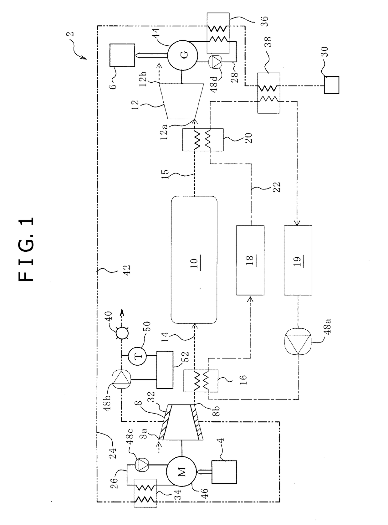
[0031]FIG. 1 is a schematic configuration diagram of a compressed air energy storage (CAES) and power generation device 2 according to a first embodiment of the present invention. In a case where a power generation facility 4 generates power by using renewable energy, the CAES power generation device 2 smooths the fluctuation of output with respect to an outside power system 6 as a supply destination and outputs power in accordance with the fluctuation of demand power in the power system 6. In addition, the power generation facility 4 is not limited to the power generation using renewable energy but may be a private power generation device such as a plant facility.

[0032]The configuration of the CAES power generation device 2 will be described with reference to FIG. 1.

[0033]The CAES power generation device 2 mainly includes four types of flow passages: an air flow passage; a heat medium flow passage, first and second cooling flow passages; and a cooling water flow passage. The air fl...

second embodiment

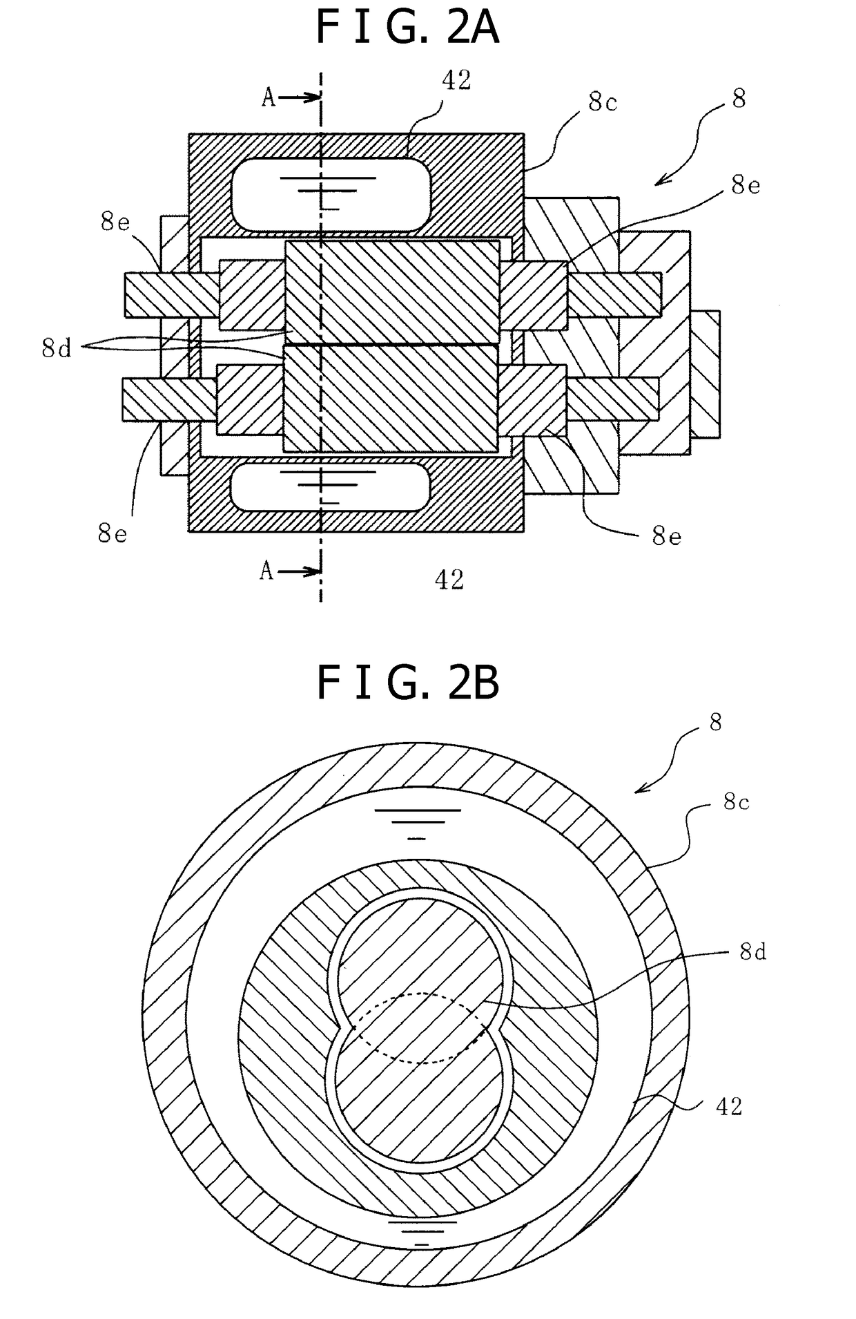
[0064]FIG. 4 is a schematic configuration diagram of the CAES power generation device 2 according to a second embodiment of the present invention. The CAES power generation device 2 according to the present embodiment is different from that of the first embodiment in that the compressor 8 is a two-stage compressor and the expander 12 is a two-stage expander and that the first heat exchanger 16 includes plural first heat exchangers, the second heat exchanger 20 includes plural second heat exchangers, and the heat storage tank 18 includes plural heat storage tanks. Other configurations of the present embodiment are substantially the same as those of the first embodiment in FIG. 1, FIG. 2A, and FIG. 2B. Therefore, the explanation of the same configurations as those shown in FIG. 1, FIG. 2A, and FIG. 2B may be omitted.

[0065]With reference to FIG. 4, the compressor 8 and the expander 12 according to the present embodiment are different from those according to the first embodiment in that...


PUM


Abstract

A compressed air energy storage and power generation device comprises a motor, a compressor, a pressure accumulation tank, an expander, and a generator. The motor is driven by a fluctuating input power. The compressor is mechanically connected to the motor and compresses air. The pressure accumulation tank is fluidly connected to the compressor and stores air compressed by the compressor. The expander is fluidly connected to the pressure accumulation tank and is driven by compressed air supplied from the pressure accumulation tank. The generator is mechanically connected to the expander and generates power to be supplied to a user. A cooling water flow path, whereby water flows inside a cooling water pipe for cooling air that is a working fluid, is provided inside a casing of the compressor. As a result, a compressed air energy storage and power generation device can be provided that is capable of efficiently reducing compressive axial force and of reducing power consumption.

Description

TECHNICAL FIELD[0001]The present invention relates to a compressed air energy storage and power generation device.BACKGROUND ART[0002]The technique referred to as a compressed air energy storage (CAES) has been known as a technique to smooth or level fluctuating and unstable generated power output. The CAES technique is to, when power is excessively generated, compress air by a compressor or the like and store energy in the form of air pressure and to reconvert the energy into electricity by an air turbine generator or the like when necessary.[0003]For example, Patent Document 1 discloses a compressed air energy storage system (compressed air energy storage and power generation device). In the compressed air energy storage system, compressed gas from which heat is recovered by a heat exchanger arranged downstream of a compressor is accumulated in a compressed gas accumulator, and the gas drawn from the accumulator is heated by the recovered heat to be supplied to a power generating ...

Claims


Application Information

Patent Timeline
Patent Type & Authority Applications(United States)
IPC IPC(8): F02C6/16
CPCF04C29/04F02C7/1435F02C7/125F02C7/143F02C6/16F02C7/141F02C7/185F02C7/16F02C7/18F02C7/12F01D25/14F05D2260/213F02C6/14Y02E50/10Y02E60/16Y02E70/30
Inventor MATSUKUMA, MASAKISAKAMOTO, KANAMISARUTA, HIROKITOSHIMA, MASATAKEKUBO, YOHEI
Owner KOBE STEEL LTD
Why Eureka
Try Eureka