Image processing device, image processing method, and surgical system

a technology of image processing and surgical system, applied in the direction of image enhancement, surgical forceps, instruments, etc., can solve the problems of affecting the surgical time, affecting the surgical accuracy of resection, and blurring of markers, so as to achieve more accurate surgical resection and shorten the time

Active Publication Date: 2018-12-13
SONY CORP
View PDF2 Cites 3 Cited by
  • Summary
  • Abstract
  • Description
  • Claims
  • Application Information

AI Technical Summary

Benefits of technology

[0017]According to the first and second aspects of the present disclosure, it is possible to perform more accurate surgical resection in a shorter time.

Problems solved by technology

Loss, disappearance, or blurring of the marker is undesirable, and therefore, the marking is performed by degenerating the tissue through burning with an energetic treatment tool or locally dyeing the tissue with a dye.
In doing so, the operator is required to make an accurate judgment, which puts a heavy burden on the operator.
Also, in a case where the operator has poor experience or the like, a large number of markers are required, which leads to increases in influence on the tissue and surgical time.
In doing so, the operator is required to have a good memory, which puts a heavy burden on the operator.

Method used


Image

  • Image processing device, image processing method, and surgical system
  • Image processing device, image processing method, and surgical system
  • Image processing device, image processing method, and surgical system

Examples


first embodiment

[0039](Example Configuration of a First Embodiment of an Endoscopic Surgical System)

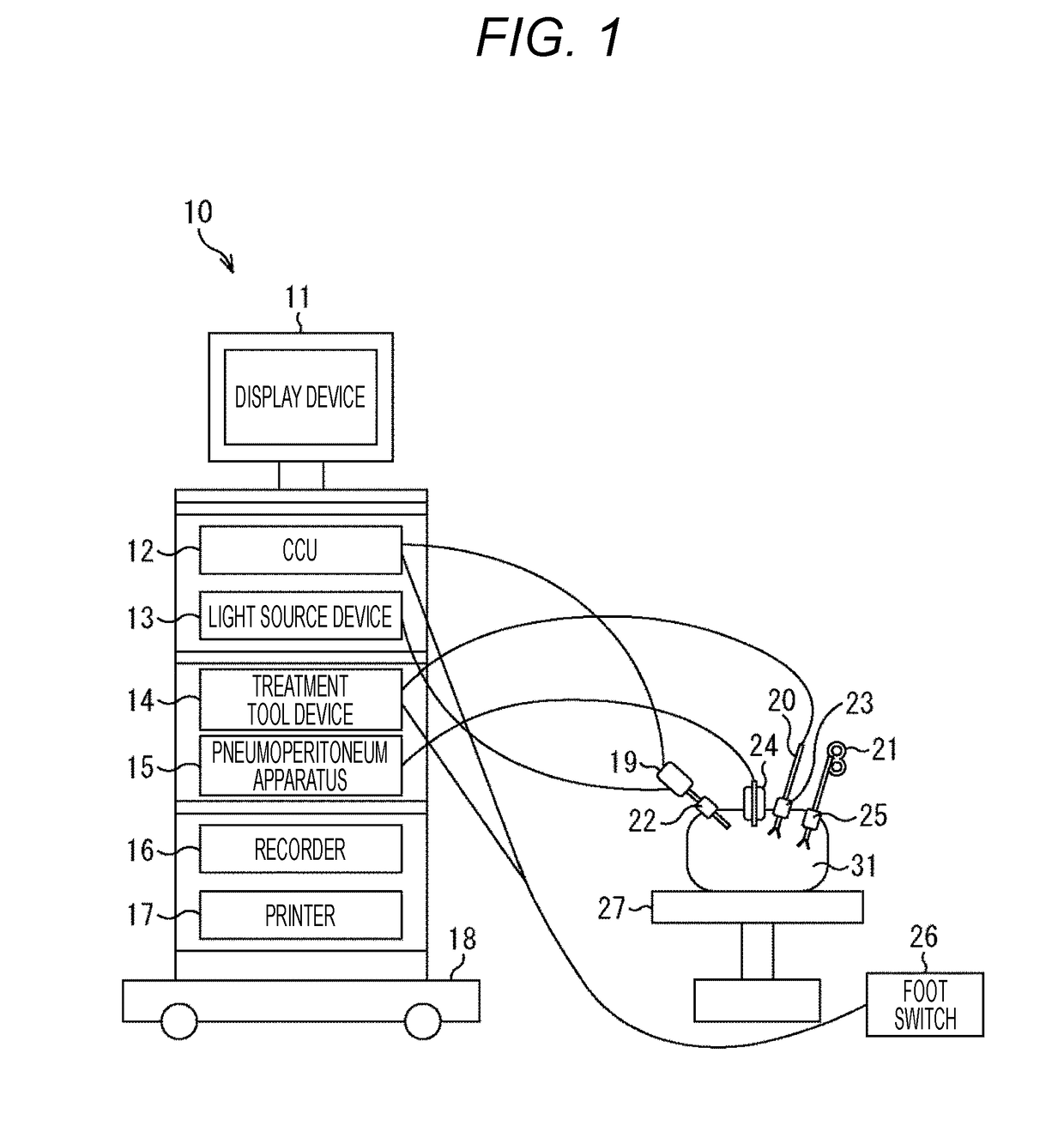
[0040]FIG. 1 is a diagram showing an example configuration of a first embodiment of an endoscopic surgical system to which the present disclosure is applied.

[0041]An endoscopic surgical system 10 includes a cart 18 on which a display device 11, a camera control unit (CCU) 12, a light source device 13, a treatment tool device 14, a pneumoperitoneum apparatus 15, a recorder 16, and a printer 17 are mounted. The endoscopic surgical system 10 also includes an endoscope (laparoscope) 19, an energetic treatment tool 20, forceps 21, trocars 22 through 25, a foot switch 26, and a patient's bed 27. The endoscopic surgical system 10 is installed in an operating room, for example, and aids the operator who is performing a laparoscopic operation on the affected area in an abdominal portion 31 of the patient lying on the patient's bed 27.

[0042]Specifically, the display device 11 of the endoscopic surgical system ...

second embodiment

[0119](Example Configuration of the CCU in a Second Embodiment of an Endoscopic Surgical System)

[0120]The configuration of a second embodiment of an endoscopic surgical system to which the present disclosure is applied is the same as the configuration of the endoscopic surgical system 10 shown in FIG. 1, except that the endoscope 19 generates mid-surgery images from more than one viewpoint, and generates a mid-surgery image from one viewpoint and a parallax image, and the CCU has a different configuration.

[0121]Therefore, only the CCU of the second embodiment will be described below.

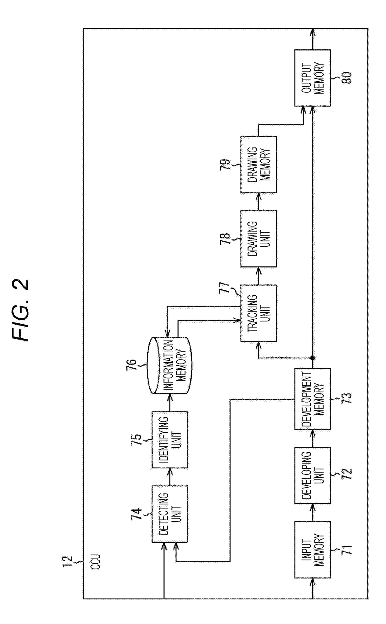
[0122]FIG. 11 is a block diagram showing an example configuration of the CCU of the second embodiment of an endoscopic surgical system to which the present disclosure is applied.

[0123]In the configuration shown in FIG. 11, the same components as those shown in FIG. 2 are denoted by the same reference numerals as those used in FIG. 2. The explanations that have already been made will not be repeated.

[0124...


PUM


Abstract

The present disclosure relates to an image processing device, an image processing method, and a surgical system with which more accurate surgical resection can be performed in a shorter time.An identifying unit identifies the type of tissue degeneration in a mid-surgery image. In accordance with the identified type of the tissue degeneration, a drawing unit draws auxiliary information for the operator, the auxiliary information being to be superimposed on the mid-surgery image. The present disclosure can be applied to an endoscopic surgical system or the like that includes a display device, a camera control unit (CCU), a light source device, a treatment tool device, a pneumoperitoneum apparatus, a recorder, a printer, an endoscope, an energetic treatment tool, forceps, trocars, a foot switch, and a patient's bed, for example.

Description

TECHNICAL FIELD[0001]The present disclosure relates to image processing devices, image processing methods, and surgical systems, and more particularly, to an image processing device, an image processing method, and a surgical system with which more accurate surgical resection can be performed in a shorter time.BACKGROUND ART[0002]In conventional surgery, in a case where resecting part of tissue including an affected area with a surgical knife or an energetic treatment tool, the operator determines a resection line in advance, and performs resection along the resection line. Therefore, the operator draws the resection line before the resection.[0003]The method of drawing the resection line may be a method of adding a marker along the resection line on the tissue. Loss, disappearance, or blurring of the marker is undesirable, and therefore, the marking is performed by degenerating the tissue through burning with an energetic treatment tool or locally dyeing the tissue with a dye.[0004...

Claims


Application Information

Patent Timeline
Patent Type & Authority Applications(United States)
IPC IPC(8): A61B34/00G06T11/20G06T7/00G06T7/73G06T7/90G06T7/20G06T5/00G06T5/50A61B1/313A61B18/00A61B90/00
CPCA61B34/25G06T11/203G06T7/0012G06T7/73G06T7/90G06T7/20G06T5/006G06T5/50A61B1/3132A61B18/00A61B90/37G06T2207/10068G06T2207/20221G06T2207/30004A61B2017/00973A61B2018/00601A61B2034/252A61B2090/373A61B1/00009A61B2090/372A61B2090/502A61B90/30A61B2090/3937A61B2034/2065A61B2018/00982A61B2018/1412G06T2207/10024G06T7/0016G06T2207/30092G06T2207/10021A61B18/1445A61B34/20
Inventor KASHIMA, KOJIHAYASHI, TSUNEOSHIRAKI, HISAKAZUTSURU, DAISUKEUEMORI, TAKESHIFUKAZAWA, KENTAROSUGIE, YUKIYAMAGUCHI, KENTA
Owner SONY CORP
Why Eureka
Try Eureka