Centrifugal separator having an intermittent discharge system

Active Publication Date: 2018-12-13
ALFA LAVAL CORP AB
View PDF0 Cites 6 Cited by
  • Summary
  • Abstract
  • Description
  • Claims
  • Application Information

AI Technical Summary

Benefits of technology

This patent describes a system for cooling the seals of a spindle using hydraulic fluid. By introducing the hydraulic fluid through the hollow spindle and allowing it to act on the bottom of the spindle, the system can achieve better cooling with higher flow rates of process medium. The hydraulic fluid can also be circulated to a heat exchange unit to prevent evaporation and maintain its heat transferring capacity during longer periods of time. By using mechanical seals instead of liquid seals, the system can better prevent oxygen transport and exert a larger lifting force on the sliding bowl bottom. The technical effects of this system include improved cooling efficiency, higher flow rates, longer maintenance intervals, and better sealing performance.

Problems solved by technology

Such hydraulically operated systems allows for opening and closing of the ports for only a fraction of a second and may result in partial or complete emptying of the content in the separation bowl.
There may thus be a problem of introducing the hydraulic liquid at a small radius from the rotational axis in such separators.

Method used


Image

  • Centrifugal separator having an intermittent discharge system
  • Centrifugal separator having an intermittent discharge system
  • Centrifugal separator having an intermittent discharge system

Examples


Embodiment Construction

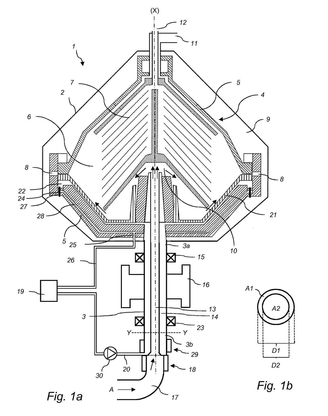
[0082]The centrifugal separator according to the present disclosure will be further illustrated by the following description of an embodiment with reference to the accompanying drawings.

[0083]FIG. 1 shows a centrifugal separator 1 for separating a liquid mixture. The separator comprises a frame 2, a hollow spindle 3, which is rotatably supported by the frame 2 in a bottom bearing 23 and a top bearing 15, and a centrifuge rotor 4. The centrifuge rotor 4 is adjoined to the upper end 3a of the spindle 3 to rotate together with the spindle 3 around an axis (X) of rotation. The centrifuge rotor 4 comprises a rotor casing 5 enclosing a separation space 6 in which a stack 7 of separation discs is arranged in order to achieve effective separation of the liquid mixture that is separated. The separation discs of the stack 7 have a frustoconical shape and are examples of surface-enlarging inserts. The stack 7 is fitted centrally and coaxially with the rotor and the discs of the stack 7 may com...


PUM


Abstract

A centrifugal separator for separation of at least two components of a fluid mixture which are of different densities includes a frame, a hollow spindle rotatably supported by the frame, a centrifuge rotor mounted to a first end of the hollow spindle to rotate together with the spindle around an axis of rotation, wherein the centrifuge rotor includes a rotor casing enclosing a separation space in which a stack of separation discs is arranged, a duct arranged to be through-flown by process medium during operation of the centrifugal separator and extending through the hollow spindle and in fluid contact with said separation space, at least one liquid outlet for discharging a separated liquid phase from the separation space, and a plurality of peripheral ports extending from the separation space through the rotor casing to a surrounding space for discharging a phase from the periphery of the separation space. The centrifuge rotor includes a sliding bowl bottom movable between a closed position, in which the peripheral ports are closed, and an open position, in which the peripheral ports are open, an inlet channel for supplying hydraulic fluid to a closing chamber between the sliding bowl bottom and the rotor casing in order to hold the sliding bowl bottom in the closed position. The centrifugal separator further includes at least one hermetic seal at a second end, other than the first end, of the hollow spindle and the inlet channel for supplying hydraulic fluid to the closing chamber extends through the hollow spindle and is further arranged such that the hydraulic fluid is in thermal contact with the at least one hermetic seal when the hydraulic fluid is being supplied to the closing chamber.

Description

FIELD OF THE INVENTION[0001]The present invention relates to the field of centrifugal separators, and more specifically to centrifugal separators having a discharge system that allows for intermittently ejecting separated sludge from a centrifuge bowl.BACKGROUND OF THE INVENTION[0002]Centrifugal separators are generally used for separation of liquids and / or solids from a liquid mixture. During operation, liquid mixture that is about to be separated is introduced into a rotating bowl and due to the centrifugal forces, heavy particles or denser liquid, such as water, accumulates at the periphery of the rotating bowl whereas less dense liquid accumulates closer to the central axis of rotation. This allows for collection of the separated fractions, e.g. by means of different outlets arranged at the periphery and close to the rotational axis, respectively.[0003]In certain types of centrifugal separators, separated sludge is discharged through a number of ports in the periphery of the sep...

Claims


Application Information

Patent Timeline
IPC IPC(8): B04B1/14B04B11/04
CPCB04B1/14B04B11/04B04B2011/046B04B11/02
Inventor HILDING, KLAS
Owner ALFA LAVAL CORP AB
Why Eureka
Try Eureka