High-pressure fuel injection pipe with connection head and method of molding connection head

a technology of connection head and high-pressure fuel injection, which is applied in the direction of corrosion prevention fuel injection, forging/pressing/hammering apparatus, etc., can solve the problems of decreasing the tightening strength of the fastening, the axial force is reduced, etc., and the outer surface is high. , the effect of preventing the axial force and reducing the axial for

Active Publication Date: 2018-12-13
USUI KOKUSAI SANGYO KAISHA LTD
View PDF0 Cites 2 Cited by
  • Summary
  • Abstract
  • Description
  • Claims
  • Application Information

AI Technical Summary

Benefits of technology

[0008]The high-pressure fuel injection pipe of the present invention achieves an excellent effect as follows. A part of the rust-inhibiting coating at the area corresponding to the neck lower part of the connection head of the narrow-diameter thick-wall steel pipe and a part of the rust-inhibiting coating at the end part of the washer in contact with the outer peripheral surface of the neck lower part of the connection head are each eliminated, and the contact part between the outer peripheral surface of the neck lower part of that connection head and the end part of the washer has a metal-to-metal contact structure, thereby a decrease in outer-surface cleanliness is prevented, and high outer-surface cleanliness can be ensured. Also, it is possible to prevent a decrease in the axial force due to exfoliation and removal of the rust-inhibiting coating and a decrease in tightening strength of a fastening nut due to creep (slip).
[0009]Also, according to the method o

Problems solved by technology

Thus, in the above-described conventional method of molding the head of the high-pressure fuel injection pipe, due to an increase in material hardness (strength), molding load, and so forth with higher pressure, protrusion due to exfoliation of the rust-inhibiting coatings 11-1 and 16A-1 such as zinc-plated layers at a connection part between the neck lower part of the connecti

Method used


Image

  • High-pressure fuel injection pipe with connection head and method of molding connection head
  • High-pressure fuel injection pipe with connection head and method of molding connection head
  • High-pressure fuel injection pipe with connection head and method of molding connection head

Examples


Embodiment Construction

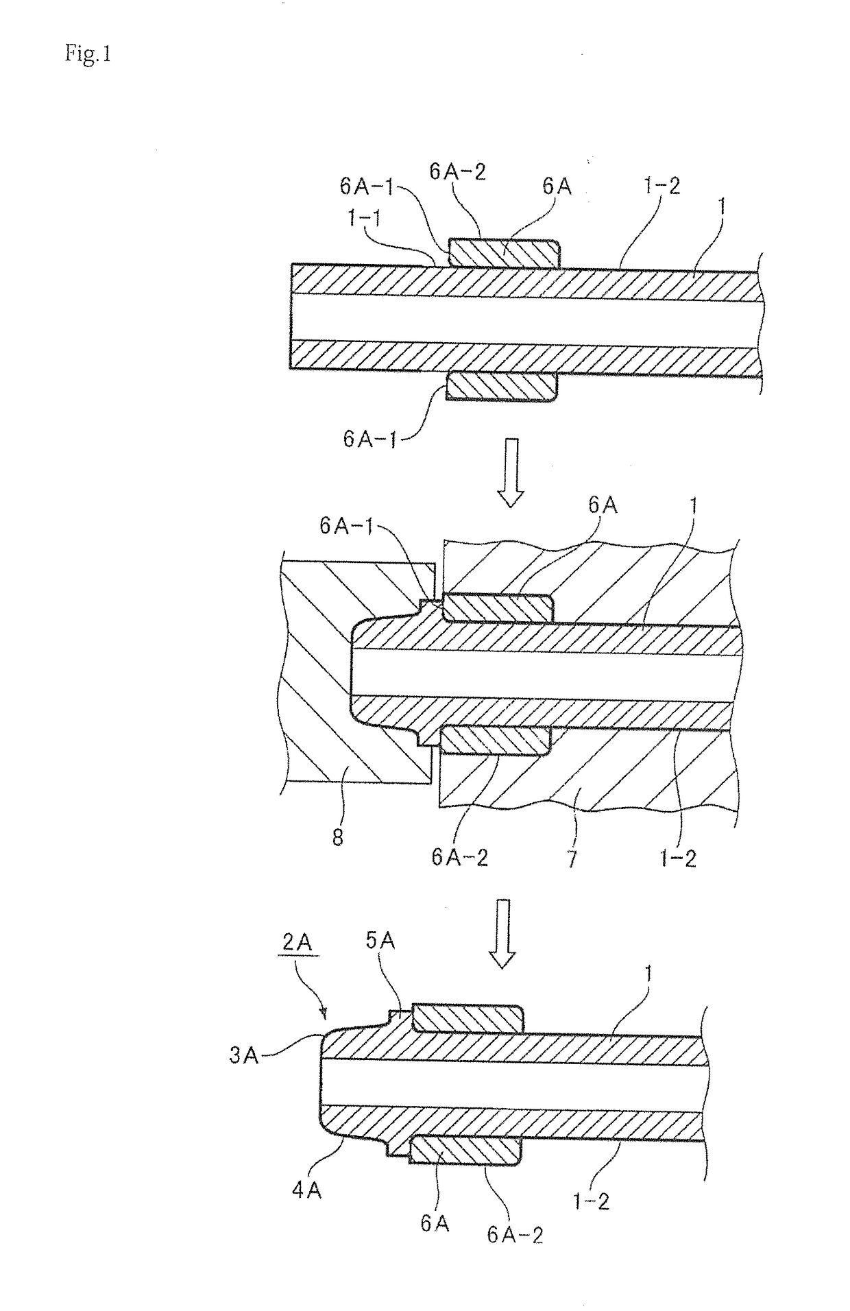
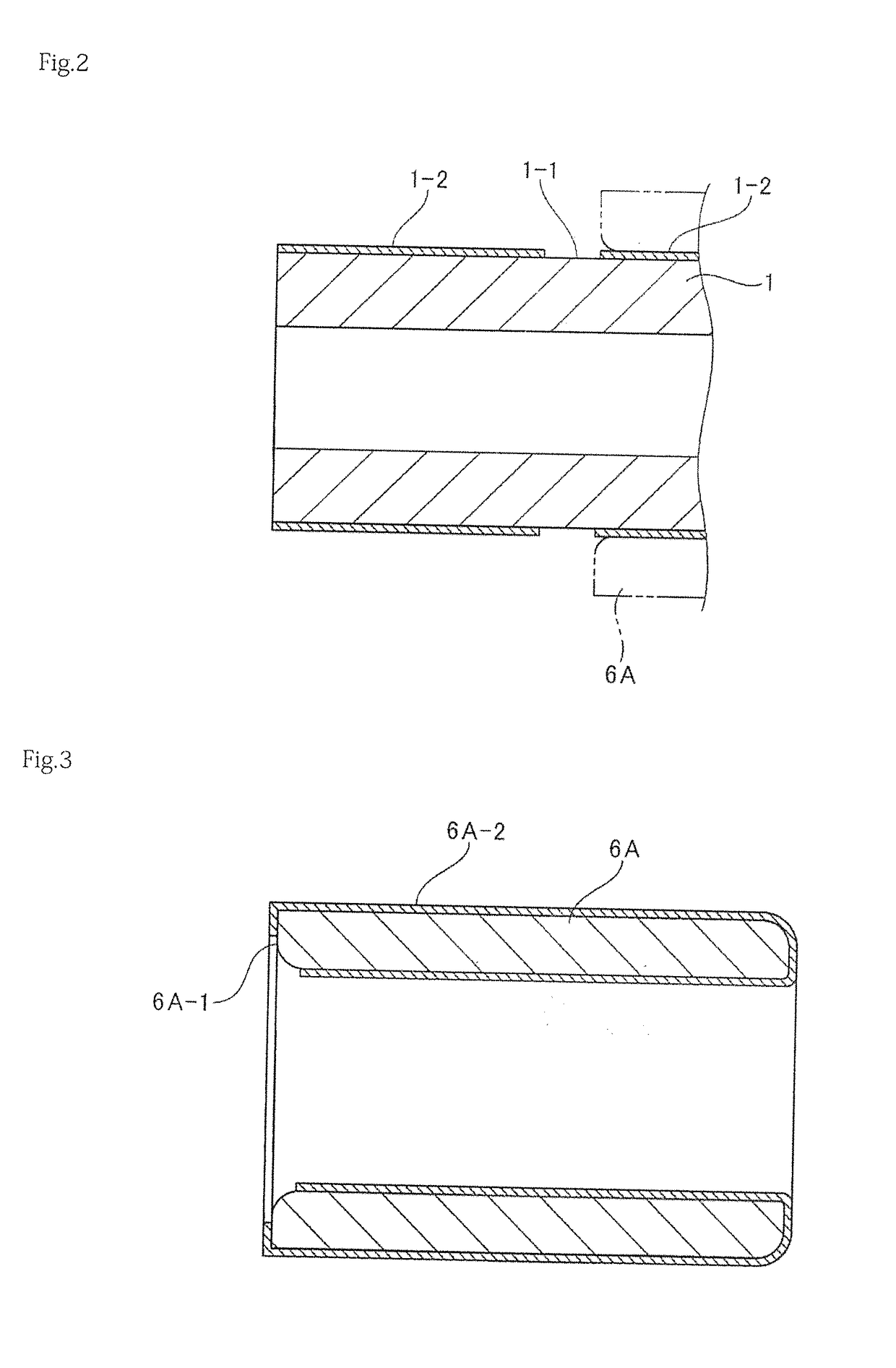
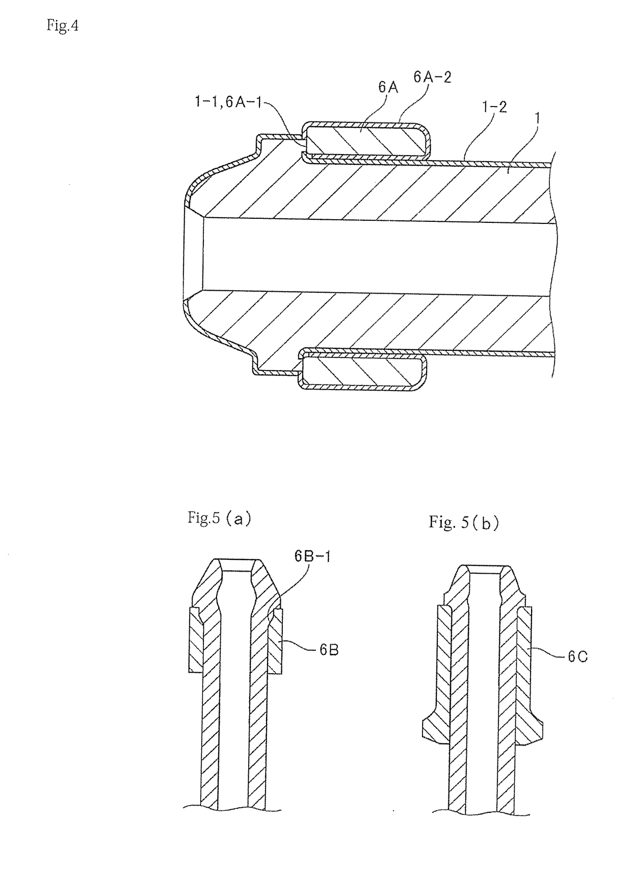
[0017]A thick-wall steel pipe 1 used in the present invention is made of a relatively narrow-diameter, thick-wall pipe made of a steel material such as stain-less steel, TRIP steel, high-pressure-pipe carbon steel, or alloy steel cut into a fixed length in advance, having a pipe diameter on the order of 4 mm to 20 mm and a wall thickness t on the order of 1 mm to 8 mm, and having an outer surface given a rust-inhibiting coating 1-2 such as a zinc-plated layer for rust inhibition, as described above. Furthermore, a washer (connection washer) 6A used in the invention has an outer surface given a rust-inhibiting coating 6A-2 such as a zinc-plated layer similar to the above.

[0018]In the method of molding a connection head of a high-pressure fuel injection pipe depicted in FIG. 1, the washer 6A externally fits in advance near the connection head of the thick-wall steel pipe 1 with a head-process margin. The thick-wall steel pipe 1 has a steel-base material section 1-1 where the rust-inhi...


PUM

PropertyMeasurementUnit
Diameteraaaaaaaaaa

Abstract

Provided is a high-pressure fuel injection pipe with a connection head which achieves an improvement in outer-surface cleanliness and prevention of a decrease in axial force and fastening strength. The pipe having, at a connection end of a narrow-diameter thick-wall steel pipe having a rust-inhibiting coating applied to an outer surface of the pipe, the connection head composed of a spherically-shaped seat surface, an annular flange, and a conical surface and having an outside peripheral surface forming formed into seat surface in a truncated conical shape or truncated arc shape for a mating seat; and a washer fitting in a neck lower part of the connection head and having a rust-inhibiting coating applied to an outer surface of the washer, wherein a contact part between the neck lower part of the connection head and an end part of the washer has a metal-to-metal contact structure without having the rust-inhibiting coating.

Description

BACKGROUNDField of the Invention[0001]The present invention relates to a high-pressure fuel injection pipe with a connection head disposed and often used as, for example, a supply path for fuel in a diesel internal combustion engine and made of thick-wall steel of a relatively thin diameter with a pipe diameter on the order of 4 mm to 20 mm and a wall thickness on the order of 1 mm to 8 mm, and a method of molding the connection head.Description of the Related Art[0002]Conventionally, as a high-pressure fuel injection pipe with a connection head of such a type, one with a washer (connection washer) fitting in a neck lower part of a connection head has been known, as exemplarily depicted in FIG. 6 (refer to Japanese Patent No. 4636515 and Japanese Patent No. 5455303. This washer-equipped high-pressure fuel injection pipe is configured of a connection head 12A formed at a connection end of a thick-wall narrow-diameter steel pipe 11 and having an outside peripheral surface formed of a ...

Claims


Application Information

Patent Timeline
IPC IPC(8): F02M55/02F02M55/00F16L19/028F02M35/10
CPCF02M55/025F02M55/005F16L19/0286F02M35/10216F02M2200/04F02M55/02B21K21/12B21K25/00B21J5/08F02M2200/05
Inventor KONDO, HIROAKITAGAMI, AKIO
Owner USUI KOKUSAI SANGYO KAISHA LTD
Why Eureka
Try Eureka