Supercharge Your Innovation With Domain-Expert AI Agents!

Battery sealing device

Active Publication Date: 2018-12-13
RENATA
View PDF0 Cites 2 Cited by
  • Summary
  • Abstract
  • Description
  • Claims
  • Application Information

AI Technical Summary

Benefits of technology

The present invention provides a battery sealing device with improved sealing properties, simplified structure, and lower cost. The device ensures the safety and performance of battery products while reducing its overall thickness and improving the use of battery space. The device uses sealing elements and a riveting manner to fully seal the battery cover plate and polar rod, as well as a sealant for low hardness and prevention of electrolyte leakage. The contact surface between the polar rod connecting plate, battery cover plate, and sealing member is provided with one or more bulges that increase the sealing property of the device during assembly. This invention is beneficial for the development and application of miniaturized battery products.

Problems solved by technology

As an important factor influencing the reliability and safety of the batteries, a battery sealing component is a technical difficulty and key point in a production process of the batteries.
At present, a common battery sealing component adopts a glass cement paper or ceramic sealing component, but it is discovered in the large quantity use process that under a high voltage chemical system environment, the glass or ceramic has an electrochemical corrosion phenomenon and a self discharging phenomenon, leading to a sealing gap, as a result, electrolyte is leaked from a polar rod terminal under the action of an internal pressure, and the long circulation service life of the battery cannot be achieved; secondly, the glass and ceramic are easy to fracture and greater in hardness, when the batteries are vibrated, the glass and ceramic are easy to break, or even fall off to cause failure in the batteries; and in addition, since the polar rod and a cover plate are made of a metal material, when the glass or ceramic sealing component is adopted to seal metal, the process is complex and the manufacture cost is high.
Under the premise that the sealing component in the application document cannot ensure the sealing property, the sealing component is thinned, the thickness of the whole sealing component cannot be reduced, therefore, the use rate of the internal space of the battery cannot be increased, and the energy density of the battery products cannot be improved.

Method used


Image

  • Battery sealing device
  • Battery sealing device
  • Battery sealing device

Examples


Embodiment Construction

[0029]The battery sealing device of the present invention is further described in detail in combination with specific embodiments and drawings.

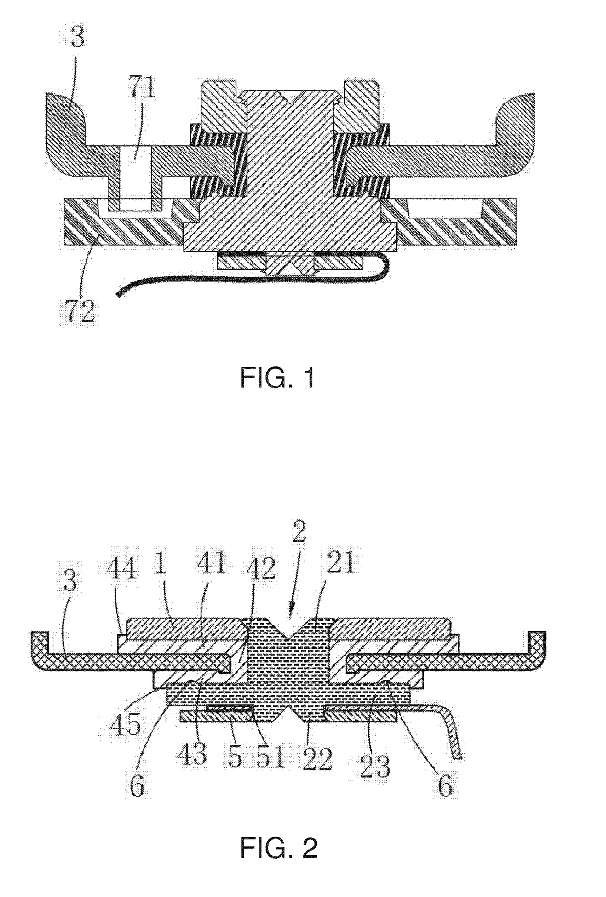
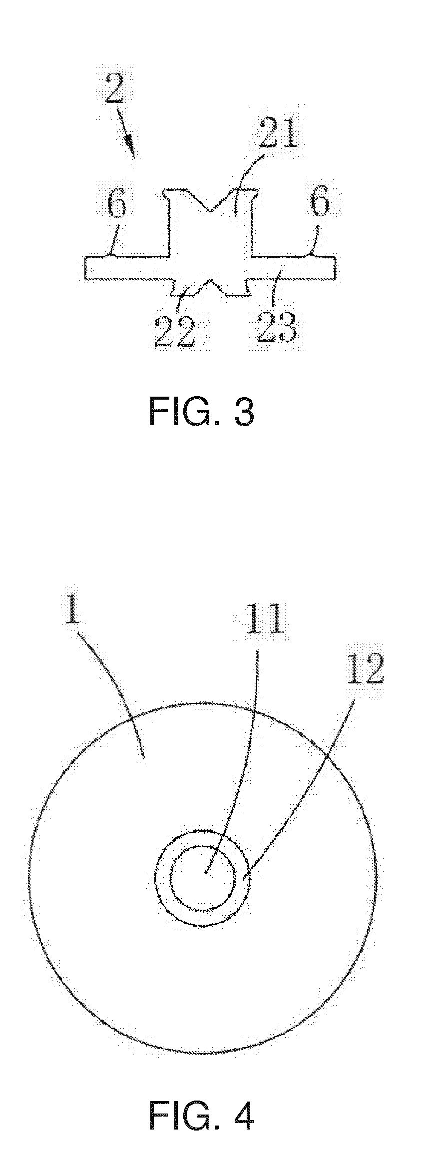
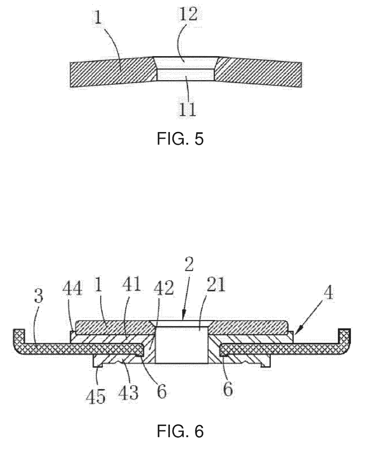
[0030]As shown in FIG. 2 and FIG. 6, in a preferred embodiment, the battery sealing device of the present invention comprises an upper pressing member 1, a polar rod 2, a battery cover plate 3 and a sealing member 4. As shown in FIG. 3, the polar rod 2 comprises a polar rod large end 21, a polar rod small end 22 and a polar rod connecting plate 23. The polar rod large end 21 and the polar rod small end 22 are both cylindrical, and the diameter of the polar rod large end 21 is larger than that of the polar rod small end 22. The polar rod large end 21 is connected to the upper surface of the polar rod connecting plate 23, and the polar rod small end 22 is connected to the lower surface of the polar rod connecting plate 23. The polar rod large end 21, the polar rod small end 22 and polar rod connecting plate 23 are of an integrally molded struct...


PUM


Abstract

A battery sealing device, including an upper pressing member, a polar rod, a battery cover plate, and a sealing member. The polar rod includes polar rod large and small ends, and a polar rod connecting plate. The upper pressing member includes an upper pressing through hole matched with the periphery of the polar rod large end. The battery cover plate includes a cover plate through hole; the polar rod large end penetrates through the upper pressing through hole and the cover plate through hole; the upper pressing member arranged above the battery cover plate. The sealing member includes an upper sealing element formed between the upper pressing member and the battery cover plate, an intermediate sealing element formed in the gap between the cover plate through hole and the polar rod large end, and a lower sealing element formed between the battery cover plate and the polar rod connecting plate.

Description

FIELD OF THE INVENTION[0001]The present invention relates to the technical field of batteries, in particular to a battery sealing device.BACKGROUND OF THE INVENTION[0002]The lithium ion batteries have the characteristics of high energy density, capability of being quickly charged and discharged and recycled, and long service life and the like, have become the mainstream of the battery energy market, and are widely applied to civil products and military products.[0003]Along with the development of the society, people have higher demands on the performance of the lithium ion batteries, in particular, the reliability and safety of the lithium ion batteries. As an important factor influencing the reliability and safety of the batteries, a battery sealing component is a technical difficulty and key point in a production process of the batteries.[0004]Along with the arising of wearable products, the demands on miniaturization and diversification of the battery products are more and more o...

Claims


Application Information

Patent Timeline
IPC IPC(8): H01M2/36H01M2/04H01M2/08H01M10/0525H01M50/147H01M50/172H01M50/184H01M50/186H01M50/188H01M50/567
CPCH01M2/365H01M2/0404H01M2/046H01M2/08H01M10/0525H01M50/154H01M50/147H01M50/152H01M50/172H01M50/184H01M50/567H01M50/188Y02E60/10H01M10/052Y02P70/50
Inventor LI, MUJIANGE, HUIMING
Owner RENATA
Features
  • R&D
  • Intellectual Property
  • Life Sciences
  • Materials
  • Tech Scout
  • Unparalleled Data Quality
  • Higher Quality Content
  • 60% Fewer Hallucinations
Learn More