Power amplifier apparatus, envelope tracking amplifier apparatus and method of amplifying a signal

a technology of power amplifier and envelope tracking, which is applied in the direction of power amplifier, high-frequency amplifier, amplifier with field-effect devices, etc., can solve the problems of compromising efficiency, affecting the efficiency of amplifiers, and the size of antennas, so as to reduce power losses

Active Publication Date: 2018-12-13
U-BLOX
View PDF1 Cites 21 Cited by
  • Summary
  • Abstract
  • Description
  • Claims
  • Application Information

AI Technical Summary

Benefits of technology

[0043]It is thus possible to provide an apparatus and method that enables optimum power transfer from an amplifier sub-circuit to a load, for example an antenna. The apparatus and method obviates the use of variable passive components to achieve optimum power transfer, thereby reducing power losses. Furthermore, adaptation to optimise power transfer can be applied in the digital domain, for example in a baseband integrated circuit.

Problems solved by technology

However, designing a wireless modem that can achieve efficient power transfer from the power amplifier to the antenna is a challenge shared by communications devices across the generations of systems.
However, the term “matched” in this context is a misnomer in the conventional “matched impedance” sense.
As most applications are size-sensitive, the antenna also has to be quite small, compromising efficiency, especially for the frequency bands below 1 GHz, which are the most useful frequency bands for coverage.
However, there is no “standard” form-factor and so Original Equipment Manufacturers (OEMs) are at liberty to try to design communications modules into their devices that occupy as little space as possible, often without much consideration for the antenna, which will have to be as small as possible.
All of the power delivered to the antenna will be radiated in the event that the antenna and the matching network are lossless, but of course inefficiencies typically exist.
However, in practice available tuneable matching networks, typically switched capacitor networks, are accompanied by undesirable losses, which reduce overall efficiency of a transmitter path.
In this respect, it is difficult to design an RF power amplifier for a communications device that can deliver high efficiency over a wide range of output powers, especially where the communications device is powered by a battery, which by its nature has limited available power, but where the actual transmit power required of the communications device varies over a wide range as dictated by the network infrastructure.
Whilst operating the power amplifier at relatively high output power back-off ensures the LTE signal is not greatly distorted when its envelope is near its peak, the efficiency of the power amplifier reduces with the increase in the amount of output power back-off applied.
However, envelope tracking places technical demands on the RF power amplifier circuit employed.
Furthermore, noise has to be minimised, because any noise, for example switching noise at the output of the modulator, appears directly as amplitude modulation of the carrier signal and increases out-of-band noise.
The design and integration process for an envelope tracking power amplifier is therefore complex.

Method used


Image

  • Power amplifier apparatus, envelope tracking amplifier apparatus and method of amplifying a signal
  • Power amplifier apparatus, envelope tracking amplifier apparatus and method of amplifying a signal
  • Power amplifier apparatus, envelope tracking amplifier apparatus and method of amplifying a signal

Examples


Embodiment Construction

[0054]Throughout the following description identical reference numerals will be used to identify like parts. For the avoidance of doubt, references herein to “linear amplifiers” should be understood to mean amplifiers operating in or arranged to operate in a linear mode of operation.

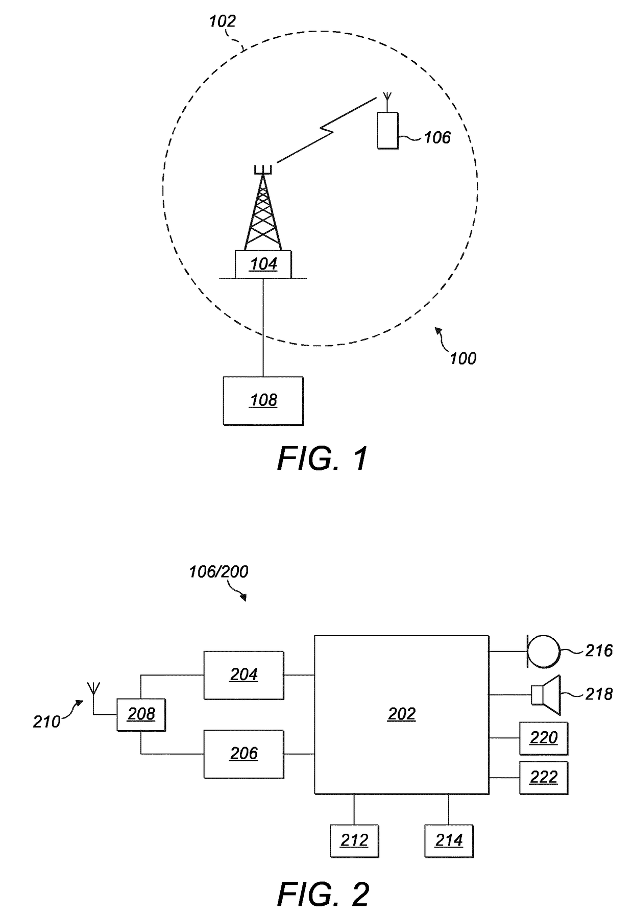
[0055]Referring to FIG. 1, in a wireless communications system, for example a Long Term Evolution (LTE) communications system 100, a communications network is supported by a plurality of cells arranged to provide wireless communications access over a geographic region. In this example, only a single cell is shown for the sake of simplicity and conciseness of description. However, the skilled person will appreciate that a greater number of cells is usually deployed throughout the communications network. In this respect, a cell 102 is supported by a base station, referred to as an evolved Node B (eNodeB) 104 in the context of the LTE communications system 100. The eNodeB 104 is capable of communicating wir...


PUM


Abstract

An amplifier apparatus (332) comprises a main linear amplifier sub-circuit (402) having a main driving signal input terminal (331) and a main amplifier output terminal (406). The apparatus also comprises an auxiliary linear amplifier sub-circuit (404) having an auxiliary driving signal input terminal (357) and an auxiliary amplifier output terminal (408). A combining network (410) is operably coupled between the main amplifier output terminal (406) and the auxiliary amplifier output terminal (408), the combining network (410) having a main-side terminal (424) and an auxiliary-side terminal (434). The main linear amplifier sub-circuit (402) is arranged to generate, when in use, a main amplified signal in response to a main driving signal applied at the main driving signal input terminal (331). The auxiliary linear amplifier sub-circuit (404) is arranged to generate, when in use, an impedance modifying signal at the auxiliary-side terminal (357) in response to an auxiliary driving signal and at substantially the same time as the main linear amplifier sub-circuit (402) generates the main amplified signal, the auxiliary linear amplifier sub-circuit (404) also being arranged to amplify substantially more than half of each wave cycle of the auxiliary driving signal.

Description

FIELD OF THE INVENTION[0001]The present invention relates to a power amplifier apparatus of the type that, for example, comprises a main linear amplifier sub-circuit and an auxiliary linear amplifier sub-circuit. The present invention also relates to an envelope tracking amplifier apparatus of the type that, for example, follows changes in an envelope of an input signal. The present invention also relates to a method of amplifying a signal, the method being of the type that, for example, comprises providing a main linear amplifier sub-circuit and an auxiliary linear amplifier sub-circuit.BACKGROUND OF THE INVENTION[0002]Power amplifiers find many uses in the field of electrical and electronic engineering. For example, power amplifiers can be found in audio amplifier circuits, servo-motor controllers, and Radio Frequency (RF) systems, such as are used in relation to wireless digital communications.[0003]In this respect, in many countries, multiple generations of wireless, for example...

Claims


Application Information

Patent Timeline
Patent Type & Authority Applications(United States)
IPC IPC(8): H03F1/02H03F3/60H03F3/16H03F3/21H03F3/193
CPCH03F1/0288H03F3/604H03F3/16H03F3/211H03F3/193H03F2200/102H03F2203/21142H03F3/189H03F3/602
Inventor HAINE, JOHN
Owner U-BLOX
Why Eureka
Try Eureka