Rotation determination in an ultrasound beam

a technology of rotation determination and ultrasound beam, which is applied in the field of rotation determination of ultrasound beam, can solve the problems that medical devices such as needles, catheters and interventional tools are often difficult to visualize in ultrasound images, and achieve the effect of improving the signal to noise ratio of signals, improving the axial range of interventional devices, and length of ultrasound receivers in the first linear sensor array

Active Publication Date: 2018-12-20
KONINKLJIJKE PHILIPS NV
View PDF0 Cites 2 Cited by
  • Summary
  • Abstract
  • Description
  • Claims
  • Application Information

AI Technical Summary

Benefits of technology

[0009]In accordance with another aspect of the invention the length of each ultrasound receiver in the first linear sensor array is greater that its width. This improves the axial range of the interventional device over which sensing can be achieved, and also improves the signal to noise ratio of signals detected by each receiver.
[0010]In accordance with another aspect of the invention, gaps between the ultrasound receivers are defined in relation to the ultrasound receiver width. This arrangement reduces the total rotational angle over which the interventional device has a reduced-sensitivity to ultrasound signals, thereby improving the accuracy with which the angular rotation can be determined.
[0011]In accordance with another aspect of the invention the first linear sensor array is wrapped around the longitudinal axis of the interventional device in the form of a spiral. The spiral wrapping arrangement provides a robust method of attaching the ultrasound transducers and the electrical interconnections associated therewith to interventional device. Moreover it provides an efficient arrangement for routing the electrical interconnections to the proximal end of the interventional device.
[0012]In accordance with another aspect of the invention the interventional device includes a second linear sensor array that is also wrapped around the interventional device circumferentially with respect to the longitudinal axis. Moreover, each gap between the ultrasound receivers in the first linear sensor array coincides with, or is aligned with, a receiver in the second linear sensor array in a lengthwise direction with respect to the axis. This arrangement improves the rotational sensitivity at rotational angles that correspond to the gaps of the first linear sensor array.
[0013]In accordance with another aspect of the invention the first linear sensor array comprises an even number of ultrasound receivers that are arranged in diametrically-opposing pairs with respect to the longitudinal axis. The ultrasound receivers are electrically connected such that ultrasound signals detected by the receivers in each pair are subtracted. This arrangement simplifies the complexity of the electrical interconnections associated with the ultrasound receivers.

Problems solved by technology

Medical devices such as needles, catheters and interventional tools are often difficult to visualize in an ultrasound image due to the specular nature of their reflectivity, particularly at unfavorable incidence angles.

Method used


Image

  • Rotation determination in an ultrasound beam
  • Rotation determination in an ultrasound beam
  • Rotation determination in an ultrasound beam

Examples


second embodiment

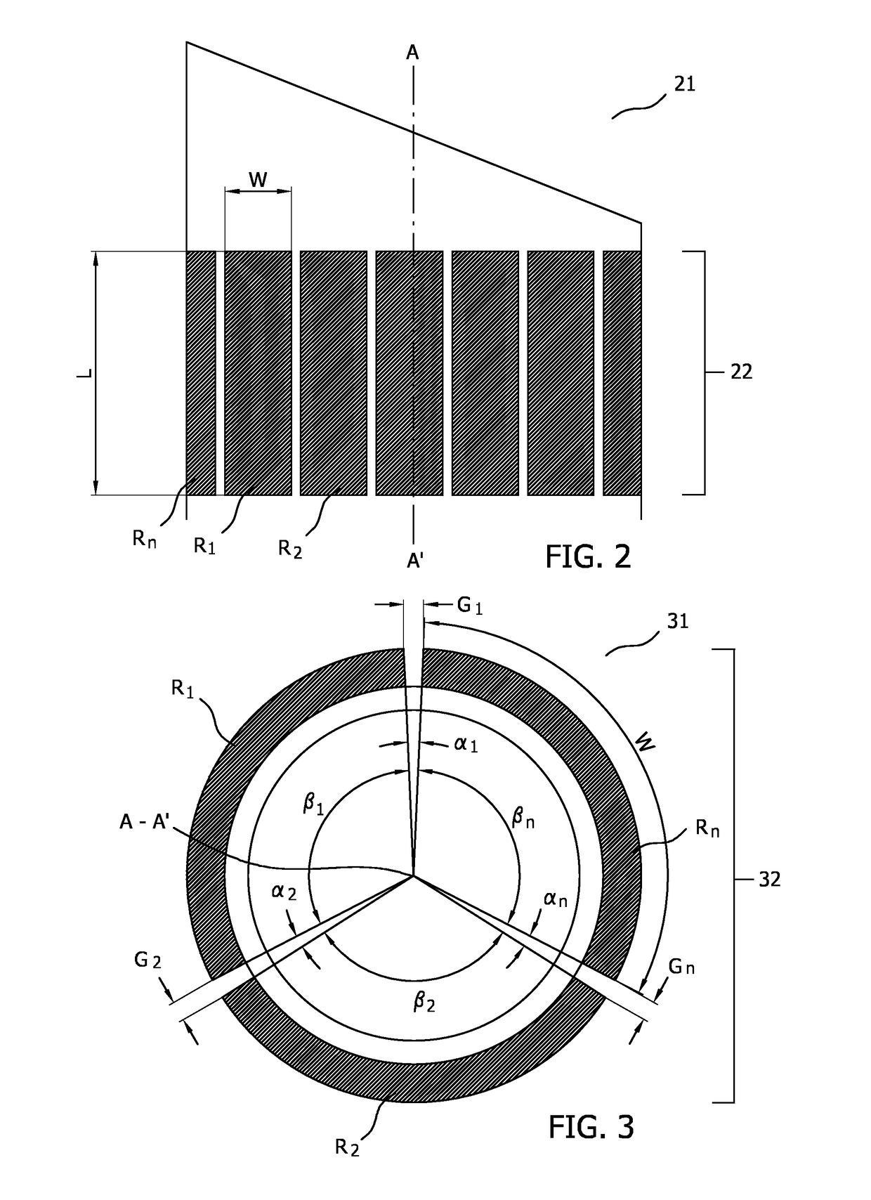
[0027]FIG. 2 illustrates in side-view the invention in which the length L of each ultrasound receiver R1, R2, Rn wrapped around longitudinal axis A-A′ of interventional device 21 is greater than its width W. A drawback of improving the angular resolution of the linear sensing array of the FIG. 1 embodiment by reducing the width of each ultrasound receiver in the array is that this reduces the signal to noise ratio of signals detected by each ultrasound receiver. However the inventors have further realized that this reduction in signal to noise ratio can in part be compensated-for by increasing the length of each ultrasound receiver. Moreover, for the interventional devices contemplated by the present invention, increasing the length of each receiver in this way permits the determination of the rotation of the interventional device along a longer length of the axis A-A′. In so doing the rotation of the device can be determined when an otherwise shorter sensor would lie outside a fini...

fourth embodiment

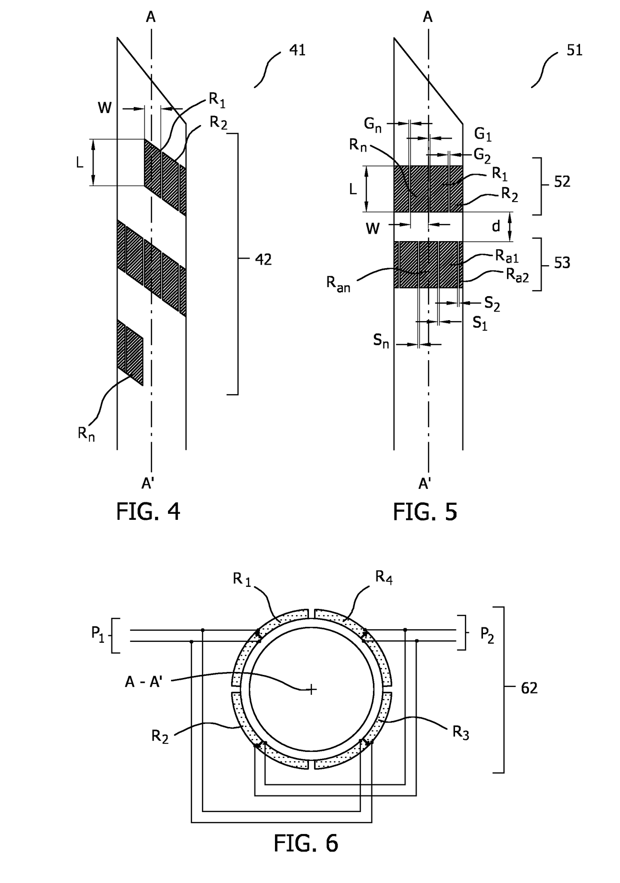
[0029]FIG. 4 illustrates in side-view the invention in which first linear sensor array 42 that includes ultrasound receivers R1 . . . n is attached to a substrate and the substrate is wrapped around longitudinal axis A-A′ of interventional device 41 in the form of a spiral. The substrate may for example be a foil that is formed from a polymer such as PET, PMMA, PVDF and the like. The substrate may include electrical wires or tracks that are electrically connected to the receivers for making electrical contact to an external electrical circuit. As described above, a drawback to improving the rotational sensitivity of the interventional device by reducing the width W of each ultrasound receiver is the reduction in signal detected by each receiver. The arrangement in FIG. 4 compensates for the reduced width of each receiver by providing a plurality of individual receivers that each view the same, or an overlapping angular range. Moreover the individual receivers can be grouped together...

fifth embodiment

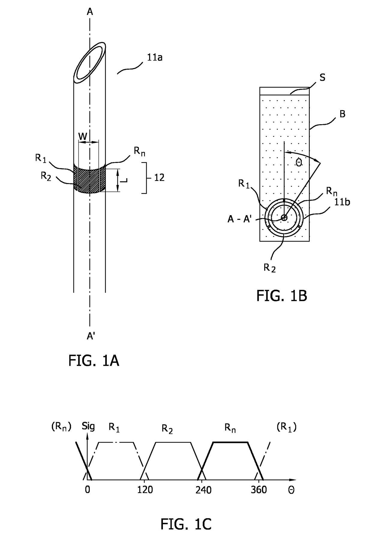
[0030]FIG. 5 illustrates in side-view the invention in which first linear sensor array 52 and second linear sensor array 53 are both wrapped around longitudinal axis A-A′ of interventional device 51. Second linear sensor array 53 includes a plurality of ultrasound receivers Ra1, Ra2, Ran, each separated by a space S1, S2, Sn. Second linear sensor array 53 is wrapped around interventional device 51 circumferentially with respect to its axis A-A′ such that each gap G1, G2, Gn, between the ultrasound receivers of the first linear sensor array 52 coincides with a receiver of the second linear sensor array Ra1, Ra2, Ran, in a lengthwise direction with respect to the axis A-A′. With reference to FIG. 1C, a relatively smaller ultrasound receiver signal is detected at rotational angles Θ that coincide with a gap between the ultrasound receivers in an array, as compared to at rotational angles that coincide with an ultrasound receiver. Thus the arrangement 51 of FIG. 5 in which ultrasound re...


PUM


Abstract

The present invention relates to determining the rotation of an interventional device in an ultrasound field. An interventional device is provided that is suitable for being tracked in an ultrasound beam of a beamforming ultrasound imaging system by correlating transmitted ultrasound signals from the beamforming ultrasound imaging system as detected by ultrasound receivers attached to the interventional device with the beamforming beam sequence of the ultrasound signals. The interventional device includes a longitudinal axis (A-A′), a first linear sensor array (12) comprising a plurality of ultrasound receivers (R1 . . . n) wherein each ultrasound receiver has a length (L) and a width (W), and wherein the array extends along the width (W) direction. Moreover the first linear sensor array (12) is wrapped circumferentially around the interventional device with respect to the axis (A-A′) such that the length (L) of each ultrasound receiver is arranged lengthwise with respect to the axis (A-A′).

Description

FIELD OF THE INVENTION[0001]The present invention relates to determining the rotation of an interventional device in an ultrasound beam. The ultrasound beam may be a beam of medical ultrasound imaging system.BACKGROUND OF THE INVENTION[0002]Medical devices such as needles, catheters and interventional tools are often difficult to visualize in an ultrasound image due to the specular nature of their reflectivity, particularly at unfavorable incidence angles.[0003]In one solution to this problem, publication WO / 2011 / 138698 discloses to attach an ultrasound receiver to a medical device. The ultrasound receiver detects ultrasound signals from the ultrasound field of an ultrasound imaging probe, and processes these signals with an ultrasound receive beamformer. The ultrasound receive beamformer is configured for one-way only beamforming of transmissive ultrasound from the ultrasound field, and is used to track the position of the ultrasound receiver and thus the medical device in relation...

Claims


Application Information

Patent Timeline
Patent Type & Authority Applications(United States)
IPC IPC(8): A61B8/08A61B8/14A61B8/00A61B34/20A61B17/34
CPCA61B8/0841A61B8/145A61B8/4488A61B8/5246A61B34/20A61B17/3403A61B2034/2063A61B2017/3413A61M2025/0166A61B2034/2065A61B8/4494A61B8/12A61B8/15A61B8/4245A61B8/445A61B8/4477A61B8/5207
Inventor DE WIJS, WILLEM-JAN ARENDKOLEN, ALEXANDER FRANCISCUS
Owner KONINKLJIJKE PHILIPS NV
Why Eureka
Try Eureka