
Wheel front burr cleaning device

a cleaning device and front burr technology, which is applied in the field of wheel grinding, can solve the problems of hardly guaranteeing the roundness and concentricity of the cap section and the rim, bringing much difficulty to removal, and low removal efficiency, so as to reduce the risk of corrosion, improve the spraying yield, and shorten the flow

Inactive Publication Date: 2018-12-20
CITIC DICASTAL
View PDF10 Cites 7 Cited by
  • Summary
  • Abstract
  • Description
  • Claims
  • Application Information

AI Technical Summary

Benefits of technology

The present invention provides a device for automatically cleaning burrs on the front side of a wheel. The device is designed for automatic production, improving efficiency and burr removal. The device includes guide rails, sliding plates, and clamping wheels for positioning and clamping the wheel. A rim burr cutter and a cap section burr cutter are used for removing burrs on the rim and the cap section of the wheel, respectively. The device can improve paint spraying yield and reduce corrosion risk. The device has the characteristics of short flow, high efficiency, and advanced process.

Problems solved by technology

In the presence of an annular circle of burrs, much difficulty is brought to removal, and the existing burr removing process hardly guarantees the roundness and concentricity of the cap section and the rim.
Besides, the removing efficiency is low, the effect is poor, and the burrs are unlikely to clean thoroughly, so a device for automatically removing wheel front burrs is urgently needed in production.

Method used


Image

  • Wheel front burr cleaning device
  • Wheel front burr cleaning device
  • Wheel front burr cleaning device

Examples


Embodiment Construction

[0020]The details and working conditions of the specific device provided by the present invention will be described below in combination with the accompanying drawings.

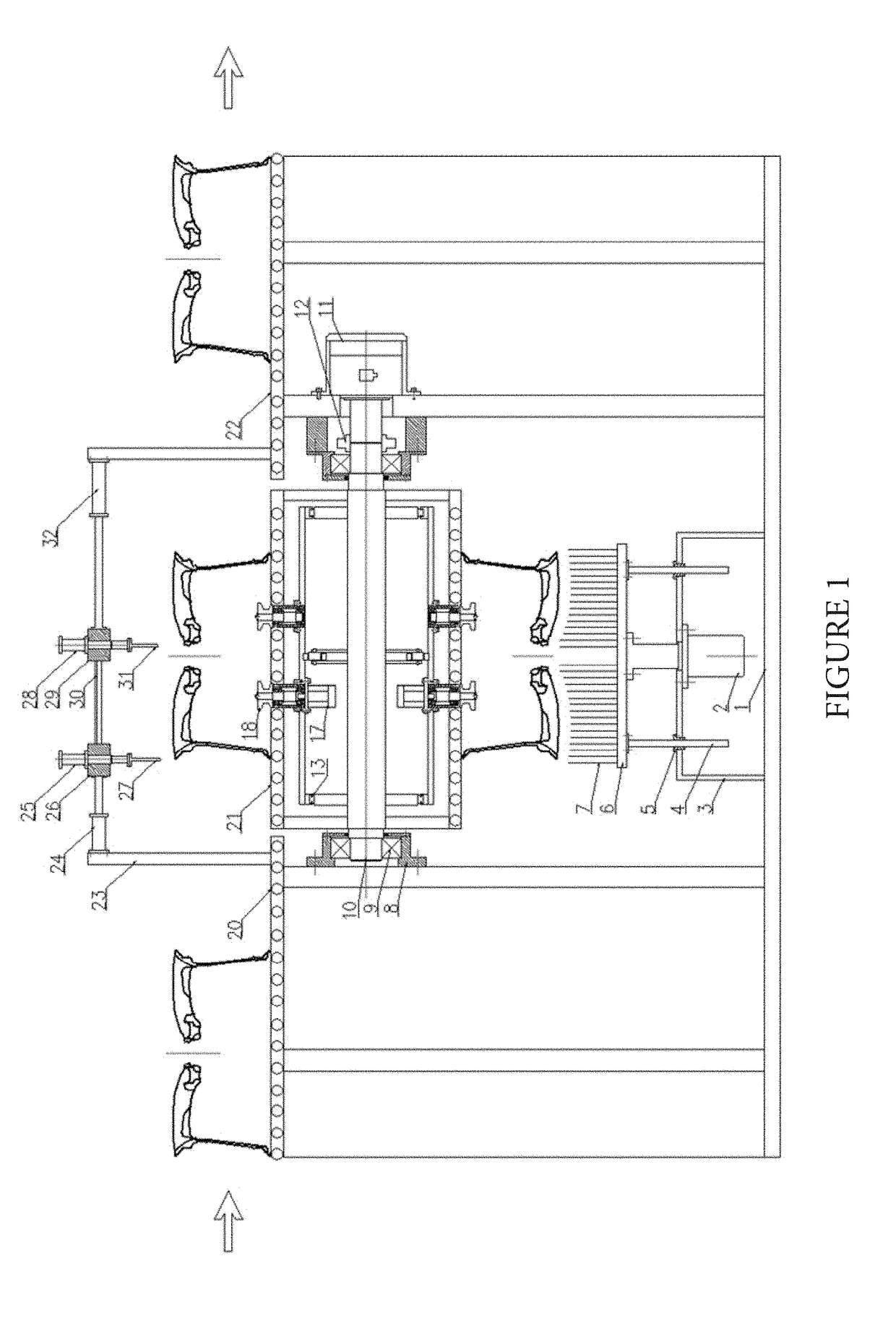
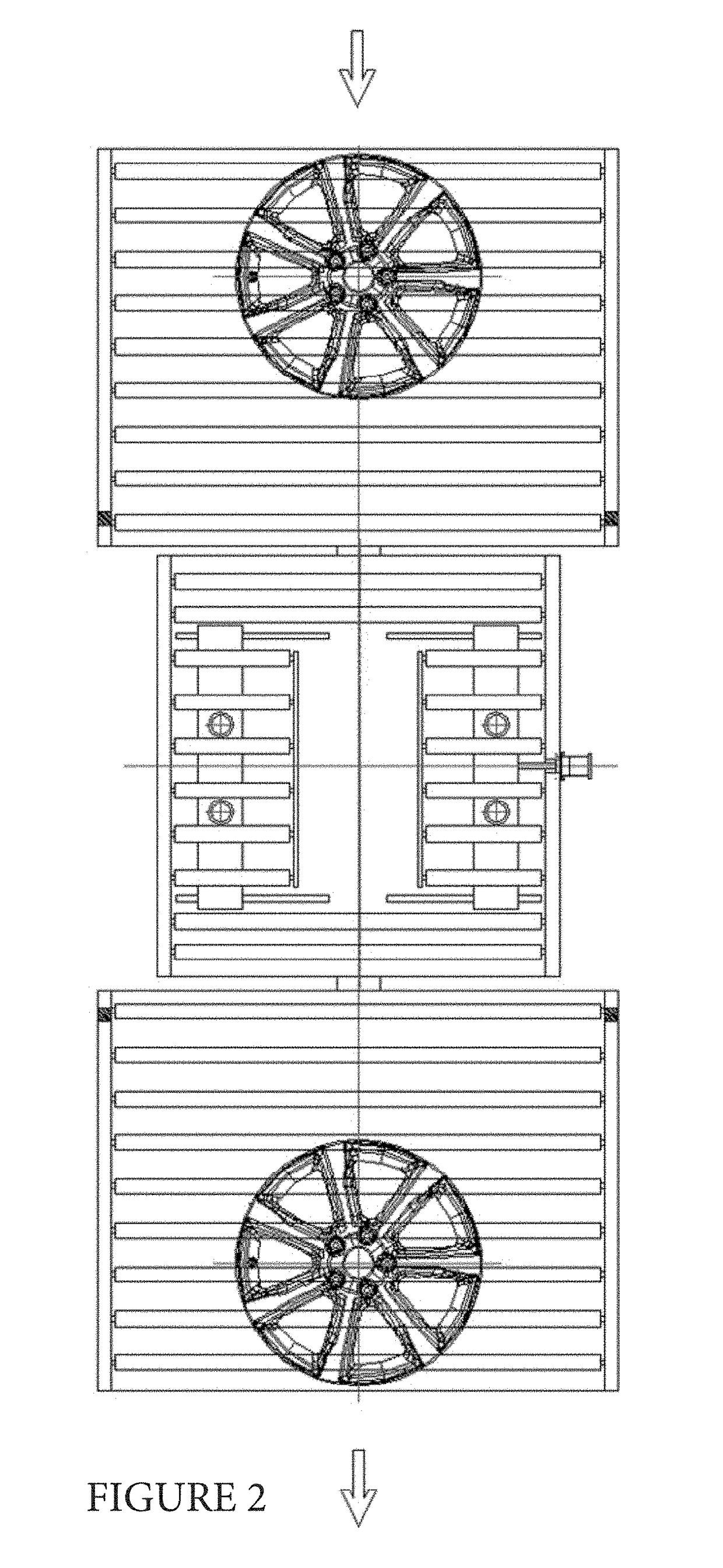
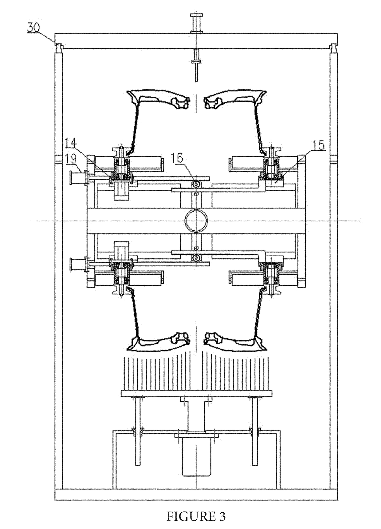
[0021]A wheel front burr cleaning device is composed of a rack 1, a lifting cylinder 2, a support frame 3, guide posts 4, guide sleeves 5, a lifting table 6, a brush 7, bearing seats 8, bearings 9, a turnover platform 10, a servo motor I 11, a coupling 12, guide rails 13, a left sliding plate 14, a right sliding plate 15, a gear rack structure 16, a servo motor II 17, clamping wheels 18, a clamping cylinder 19, a feeding roller bed 20, a working roller bed 21, a discharge roller bed 22, a cutter system support frame 23, a rim burr cutter adjusting cylinder 24, a rim burr cutter feeding cylinder 25, a left sliding table 26, a rim burr cutter 27, a cap section burr cutter feeding cylinder 28, a right sliding table 29, adjusting guide rails 30, a cap section burr cutter 31 and a cap section burr cutter adjusting cylinder...


PUM


Abstract

Disclosed is a wheel front burr cleaning device. The device is composed of a rack (1), a lifting cylinder (2), a support frame (3), guide posts (4), guide sleeves (5), a lifting table (6), a brush (7), bearing seats (8) and the like, wherein a servo motor I (11) is fixed on the side of the rack (1), the output end of the motor is connected with a turnover platform (10) via a coupling (12), the middle part of the turnover platform (10) is a cuboid, circular shafts are arranged on the left side and right side of the turnover platform (10), and the shafts are matched with bearings (9); and the structures above and below the turnover platform (10) are completely consistent, wheel positioning clamping rotating systems are distributed symmetrically, and the servo motor I (11) controls the turnover platform (10) to rotate 180 degrees every time, thereby realizing cyclic switching of the positioning clamping systems above and below the turnover platform (10).

Description

RELATED APPLICATION[0001]This application claims priority to Chinese Patent Application No. 201710468944.5, filed on Jun. 20, 2017, which is hereby incorporated by reference in its entirety.FIELD OF THE INVENTION[0002]The present invention relates to the technical field of wheel grinding, and specifically, to a device for cleaning burrs after wheel machining.BACKGROUND OF THE INVENTION[0003]After wheel machining, burrs on the front side are mainly at the rim and the cap section. In the presence of an annular circle of burrs, much difficulty is brought to removal, and the existing burr removing process hardly guarantees the roundness and concentricity of the cap section and the rim. Besides, the removing efficiency is low, the effect is poor, and the burrs are unlikely to clean thoroughly, so a device for automatically removing wheel front burrs is urgently needed in production.SUMMARY OF THE INVENTION[0004]The present invention is aimed at providing a device for automatically cleani...

Claims


Application Information

Patent Timeline
Patent Type & Authority Applications(United States)
IPC IPC(8): B24B5/44B24B9/04B24B5/35B24B55/06
CPCB24B5/44B24B9/04B24B5/35B24B55/06B24B5/355B23C3/04B24B27/0023B24B27/0069B24B29/005B24B29/04B24B41/067B26D3/02
Inventor LIU, HUIYINGSHI, BAOJUNLI, ZHEN
Owner CITIC DICASTAL
Learn More