Reduced drag projectiles

a projectile and drag technology, applied in the field of low caliber firearm bullets, can solve the problems of increased drag in the air of bullets, increased blood loss, and inability to commercialize bullets with grease grooves, and achieve the effect of reducing the needed energy to deform, reducing the need for energy, and reducing the surface area

Active Publication Date: 2018-12-20
FEDERAL CARTRIDGE
View PDF19 Cites 16 Cited by
  • Summary
  • Abstract
  • Description
  • Claims
  • Application Information

AI Technical Summary

Benefits of technology

[0005]Adding grooves to a low caliber bullet can result in greater muzzle velocity. Such grooves provide less surface area of metal to metal contact between bullet and rifled barrel and can also reduce the needed energy to deform the bullet surface by the barrel rifling, both of which can provide an increase in muzzle velocity. However, providing such grooves can increase the bullet drag in air. Bullets are designed to have minimal decrease in velocity as they travel down range as quantified by a “ballistic coefficient”. The higher the ballistic coefficient the less drag a bullet has traveling down range. It is estimated that each circumferential groove decreases the ballistic coefficient of a rifle bullet by about 3.5%.
[0006]Embodiments of the invention include an elongate rifle bullet with a plurality of circumferential grooves having overmolded polymer therein defining embedded polymer rings. Embodiments of the invention include cartridges with propellant and such bullets. In one or more embodiments, the bullet has a body portion and a converging nose portion, the nose and body being monolithic. In one or more embodiments the nose may be hollow and the body solid. The polymer rings have an outer surface that is flush with, that is, conforming to the outer surface of the body with the same or substantially the same radius. A feature and advantage of embodiments is that the metal to metal contact between the bullet and the barrel is reduced while not diminishing the ballistic coefficient of the bullet.

Problems solved by technology

Bullets with grooves filled with grease are not commercially feasible in today's market.
However, providing such grooves can increase the bullet drag in air.
The relatively large exit wound may cause greater blood loss leading to a faster kill.

Method used


Image

  • Reduced drag projectiles
  • Reduced drag projectiles
  • Reduced drag projectiles

Examples


Embodiment Construction

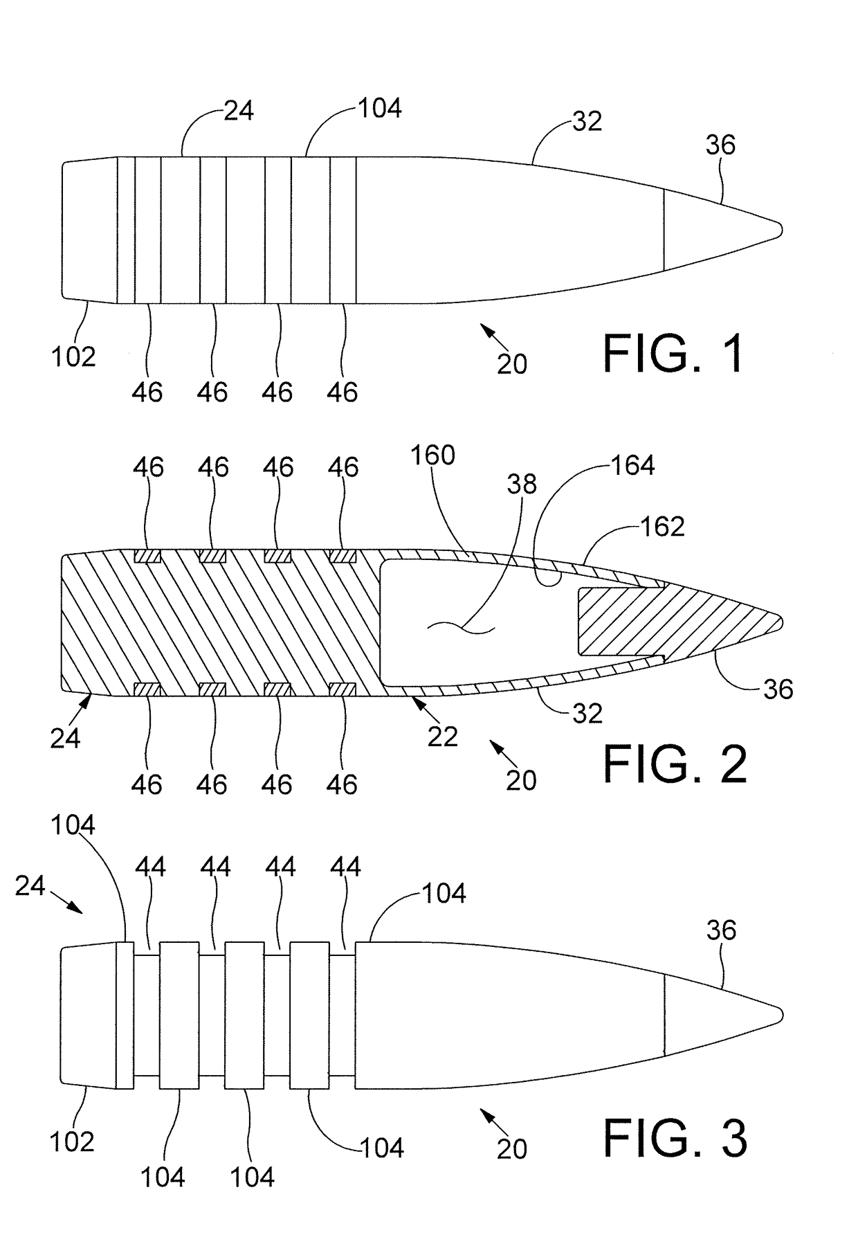
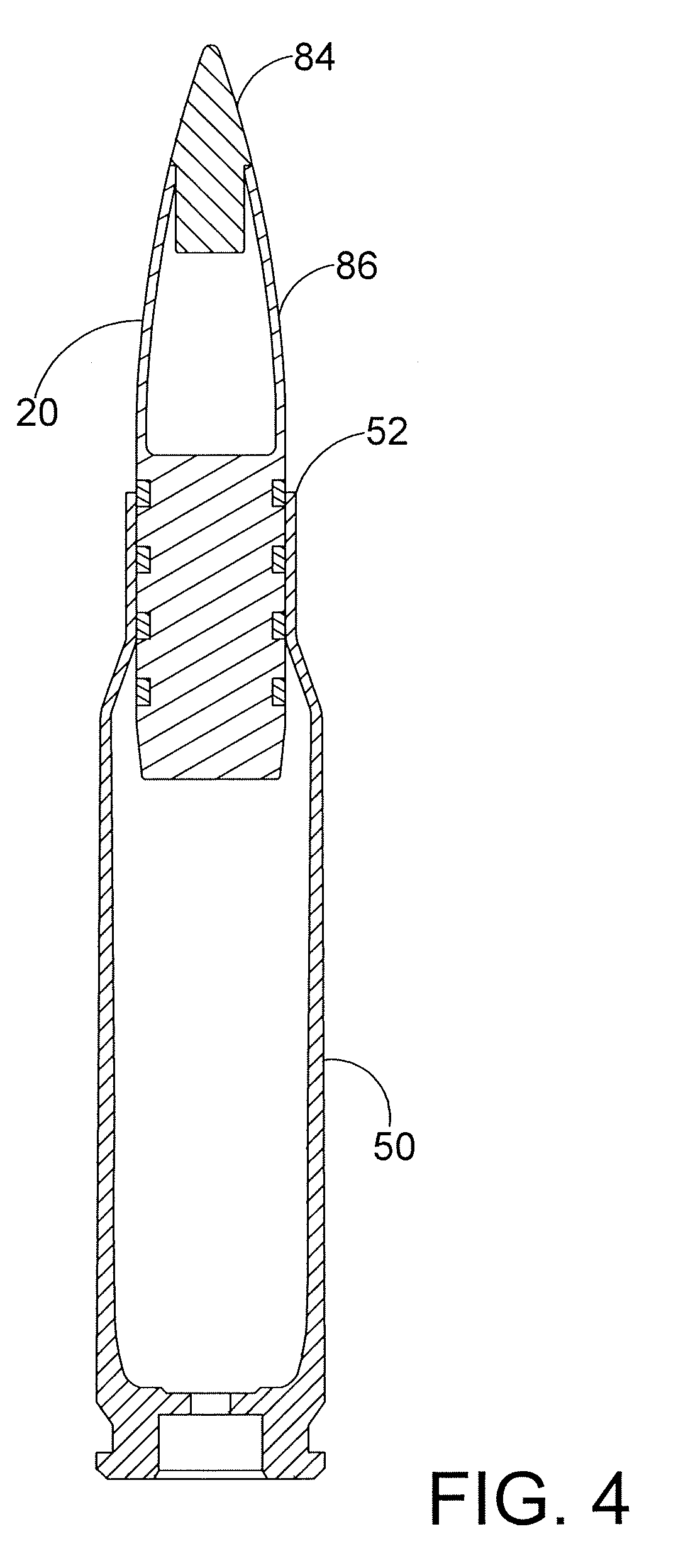
[0069]Referring to FIGS. 1-3, a side view of rifle bullet 20 is depicted according to one or more embodiments. The bullet 20 has a body 22 with a main body portion 24 and a nose portion 32. In one or more embodiments, the main body portion 24 comprises a tail portion 102 and a barrel engaging portion 104. Additionally, the bullet 20 may include a polymer tip 36 in a forward cavity 38 of the nose portion 32. The bullet main body portion and nose portion in one or more embodiments are monolithic. In one or more embodiments, the bullet 20 has one or more circumferentially extending grooves 44. The grooves having polymer bands 46 therein formed by overmolding. The grooves may have “square” corners but also other shapes including an undercut shape are within the scope of the invention. That is, the cross section of the groove and the band molded therein may be, by way of example and not limitation, trapezoidal shaped in lateral cross-section and / or a C-shape cut. The grooves are contempl...


PUM


Abstract

A cartridge comprising an elongate rifle bullet with a plurality of circumferential grooves having overmolded polymer therein defining embedded polymer rings. The cartridge further having a case and propellant. The polymer rings have an outer surface that is flush with, that is, conforming to the outer surface of the body. The polymer may have be selected to have a favorable coefficient of friction with respect to the barrel. The bands offering reduction of the metal to metal contact between the bullet and the barrel while not diminishing the ballistic coefficient of the bullet.

Description

[0001]This application is a continuation-in-part of U.S. Utility patent application Ser. No. 15 / 331,631, filed on Oct. 21, 2016, now U.S. patent Ser. No. 10 / 001,355. Said patent claims priority to U.S. Provisional Application No. 62 / 244,588 filed on Oct. 21, 2015. The above applications and patent are incorporated by reference herein.FIELD[0002]The present disclosure relates to low caliber firearm bullets, that is, .50 caliber and less, and more specifically, to cartridges and rifle bullets.BACKGROUND OF THE DISCLOSURE[0003]Rifle bullets have a conventional elongate shape with pointed tip. The elongate shape adds stability during flight and increases the kinetic energy for a particular bullet size. The elongate shape also increases metal surface area contacting the metal barrel during firing and the metal to metal, barrel to bullet, friction can reduce the muzzle velocity of the bullet. Bullets are known having rearward ends with a boat tail and circumferential grooves, both of whic...

Claims


Application Information

Patent Timeline
Patent Type & Authority Applications(United States)
IPC IPC(8): F42B14/02F42B5/02
CPCF42B14/02F42B5/025F42B10/46F42B12/74
Inventor PETERSON, BRYAN P.HURT, RICHARDLASKA, DAVID M.GOODLIN, DREW L.
Owner FEDERAL CARTRIDGE
Why Eureka
Try Eureka