Improvements in and relating to remote sensing

a remote sensing and remote sensing technology, applied in the field of remote sensing systems and methods, can solve the problems of difficult to utilise raman techniques in environments, and limited use of raman lidar methods, so as to enhance buoyancy, enhance retro-reflection efficiency, and facilitate the effect of manufacturing the cor

Inactive Publication Date: 2018-12-20
BAE SYSTEMS PLC
View PDF0 Cites 2 Cited by
  • Summary
  • Abstract
  • Description
  • Claims
  • Application Information

AI Technical Summary

Benefits of technology

[0007]At its most general, the invention provides a system and method for remote sensing using retro-reflective optical elements placed in an environment to be monitored. These are illuminated by a remote light source such that retro-reflected light may be detected for subsequent analysis as desired to monitor / detect properties of the remote environment. The invention proposes providing a retro-reflective optical element(s) possessing a core encased, embedded or immersed within an optically less dense (e.g. less refractive) cladding, covering, shell or jacket bearing a reflective optical coating. The result enables efficient convergence of incoming light towards the reflective optical coating. This greatly enhances the efficiency of retro-reflection of incident light and in preferred embodiments may also enhance buoyancy if / when the optical elements are placed in a fluid or liquid (e.g. water) environment.
[0008]In a first of its aspects, the present invention may provide a system for remotely sensing light emanating from within a monitored environment, the system comprising one or more retro-reflective optical elements bearing an optically reflective optical coating upon a surface thereof and positionable within the environment to be monitored. A light source is arranged to direct a beam of light at the optical element(s), and a detector is arranged to receive from the optical element(s) light (e.g. retro-reflected) returned by the optical coating in response to the beam of light and to detect a property of the monitored environment according to said returned light (e.g. retro-reflected) response. One, some or each optical element includes a body comprising a core part of positive optical power having a first refractive index and clad by a cladding part having a second refractive index of value less than that of the first refractive index. The optical coating is arranged over an outer surface of the cladding part thereat to receive light which has been at least partially converged by the core part for subsequent retro-reflection. The first refractive index may be substantially uniform in value throughout the volume of the core part. The second refractive index may be substantially uniform in value throughout the volume of the cladding part. In this way, the core part and / or the cladding part may be formed of material possessing a substantially spatially uniform refractive index throughout the core / cladding in question. Uniformity of refractive index (and therefore of density) permits consistent refraction / focussing throughout the optical element. This also allows for use of simpler and cheaper manufacture of the core and / or cladding parts and, therefore, the optical element(s) as a whole. When employing very many optical elements, when it is desired to dispersed them over a wide area being monitored, or when a strong and / or spatially dense / highly-resolved return signal is desired, this efficiency is especially beneficial.
[0009]Desirably, the invention may provide a retro-reflective optical element(s) bearing a photo-luminescent material, and provide a source of excitation light for irradiating the photo-luminescent material remotely when the optical element is placed within a monitored environment. The retro-reflective action of the optical element permits efficient return of photo-luminescent light generated by the photo-luminescent material in response to the excitation light. The photo-luminescent response of the photo-luminescent material is preferably variable according to changes in a property of the photo-luminescent material inducible by changes in the monitored property of the monitored environment.

Problems solved by technology

This makes the Raman technique more difficult to utilise in environments where transmission windows are restricted (e.g. underwater).
Consequently, Raman techniques are limited in their use.
Remote sensing techniques such as Brillouin and Raman lidar methods tend to be limited by the very low levels of molecular backscatter they produce in a monitored environment, in use.
However, this method depends upon to ability to place a physically steady and controllable light source in a desired location and, clearly, this may not be possible or desirable in some circumstances, especially in marine environments.

Method used


Image

  • Improvements in and relating to remote sensing
  • Improvements in and relating to remote sensing
  • Improvements in and relating to remote sensing

Examples


Embodiment Construction

[0045]In the drawings, like items are assigned like reference symbols.

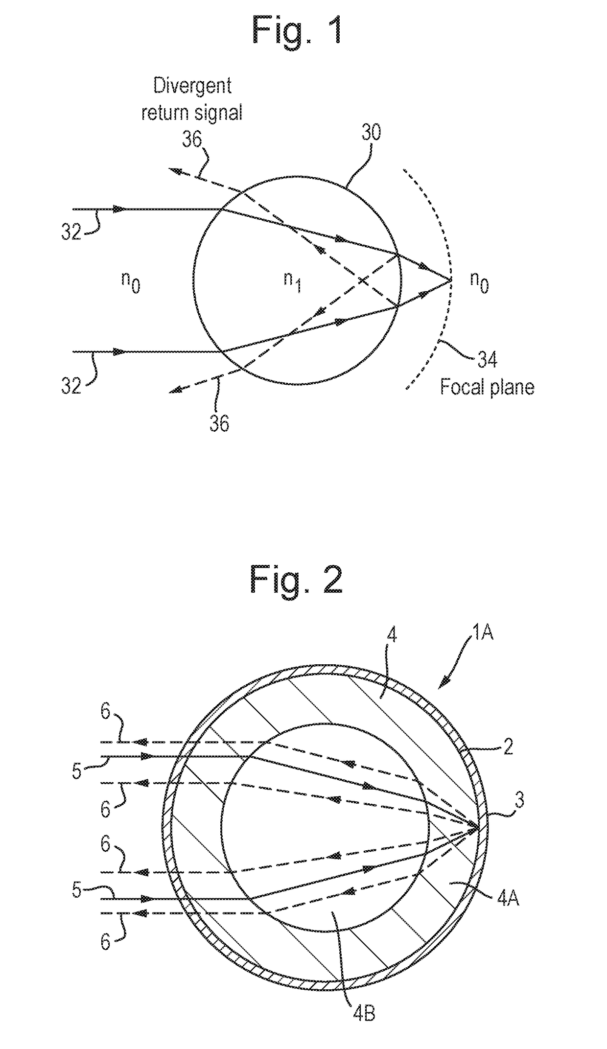
[0046]FIG. 1 schematically illustrates an optical glass bead 30 formed from a sphere of glass having refractive index n1 immersed within an environment having a refractive index n0 and illuminated with a beam of visible light 32 which enters the body of the spherical bead at one side and exits the body of the bead at the opposite side. The positive optical power of the glass bead means that light passing through it is converged towards the surface of the bead at its exit side. However, complete convergence is not achieved at the surface of the exit side due to insufficient refractive power of the glass at the surface of the entry side of the glass bead at the interface between the glass of refractive index n1 and the environment of refractive index n0. The result is that the focal plane 34 of the glass bead lies outside the bead.

[0047]A further consequence of the insufficient refractive power of the glass is that ...


PUM

PropertyMeasurementUnit
decay timeaaaaaaaaaa

Abstract

A system for remotely sensing light emanating from within a monitored environment. The system comprises one or more retro-reflective optical elements bearing a reflective optical coating upon a surface thereof and positionable within the environment to be monitored. A light source is arranged to direct a beam of light at the optical element(s), and a detector is arranged to receive from the optical element(s) light returned by the optical coating in response to the beam of light and to detect a property of the monitored environment according to said returned light. The optical element(s) includes a body comprising a core part of positive optical power and clad by a cladding part. The refractive index of the core is greater than that of the cladding. The optical coating is arranged over the cladding to receive light which has been at least partially converged by the core part for subsequent retro-reflection.

Description

FIELD OF THE INVENTION[0001]The invention relates to remote sensing systems and methods. In particular, though not exclusively, the invention relates to free-space optical methods of remote sensing.BACKGROUND[0002]Conventional free-space optical remote sensing techniques rely on irradiating a monitored environment, with light intended to interact with that environment in a manner which produces a detectable change. In particular, by analysing the light that has been backscattered by target molecules within the monitored environment, such as water molecules, information about the state of those molecules may be gleaned. By inference, one may deduce the state of the environment of which those molecules form a part. For example, spectral shifts in the optical frequency of return optical signals resulting from inelastic optical interactions with a target molecule may be detected. These shifts can be either to a lower frequency (Stokes) or to a higher frequency (Anti-Stokes). By using a ...

Claims


Application Information

Patent Timeline
Patent Type & Authority Applications(United States)
IPC IPC(8): G01N21/64G02B5/12
CPCG01N21/643G01N21/6489G01N21/6408G02B5/12G01N2021/6432G01N2021/6439G01N2021/1793G01N2201/0636G01N21/77G01N2021/7786G02B5/128
Inventor LAYCOCK, LESLIE CHARLES
Owner BAE SYSTEMS PLC
Why Eureka
Try Eureka