Drive unit, lithography apparatus, cooling method, and article manufacturing method
- Summary
- Abstract
- Description
- Claims
- Application Information
AI Technical Summary
Benefits of technology
Problems solved by technology
Method used
Image

Examples
first embodiment
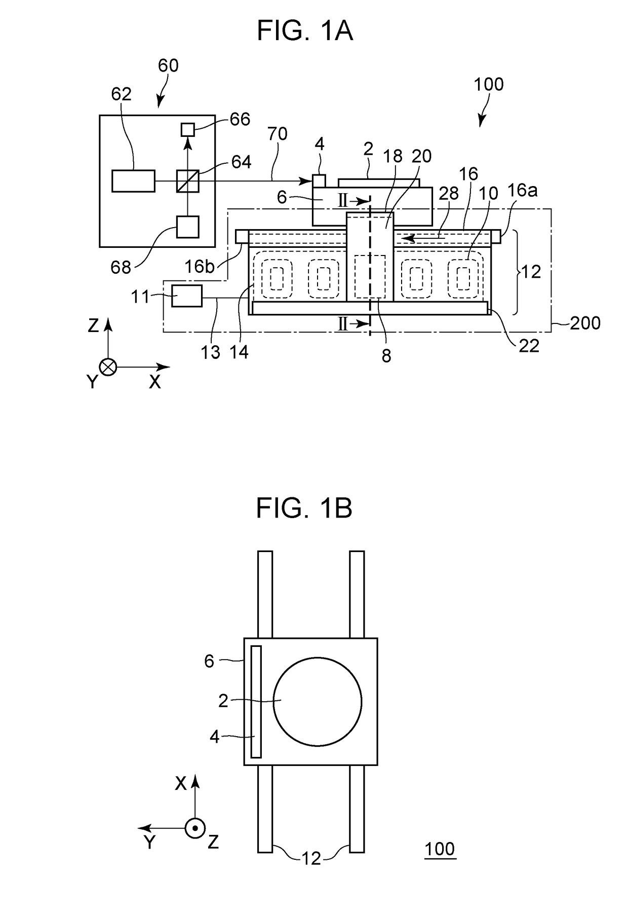
[0017]FIG. 1A is a front view illustrating a configuration of a stage device (positioning device) 100 and an interferometer 60 that measures the position of the stage device 100 according to a first embodiment. FIG. 1B illustrates the stage device 100 as viewed from the positive side in the Z-direction. An axis in the vertical direction is a Z-axis, and two axes orthogonal to each other in a plane perpendicular to the Z-axis are an X-axis and a Y-axis.
[0018]The stage device 100 is a device that determines the position of an object 2. The stage device 100 includes a stage (object) 6 having the object 2 and a mirror 4 thereon, and a drive unit200 configured to drive the stage 6. The mirror 4 extends in the Y-axis direction and reflects a measurement beam from the interferometer 60.
[0019]The drive unit 200 includes an electromagnetic actuator including a magnet 8 and a coil 10 and configured to be driven by allowing current to flow through the coil 10. The electromagnetic actuator acco...
second embodiment
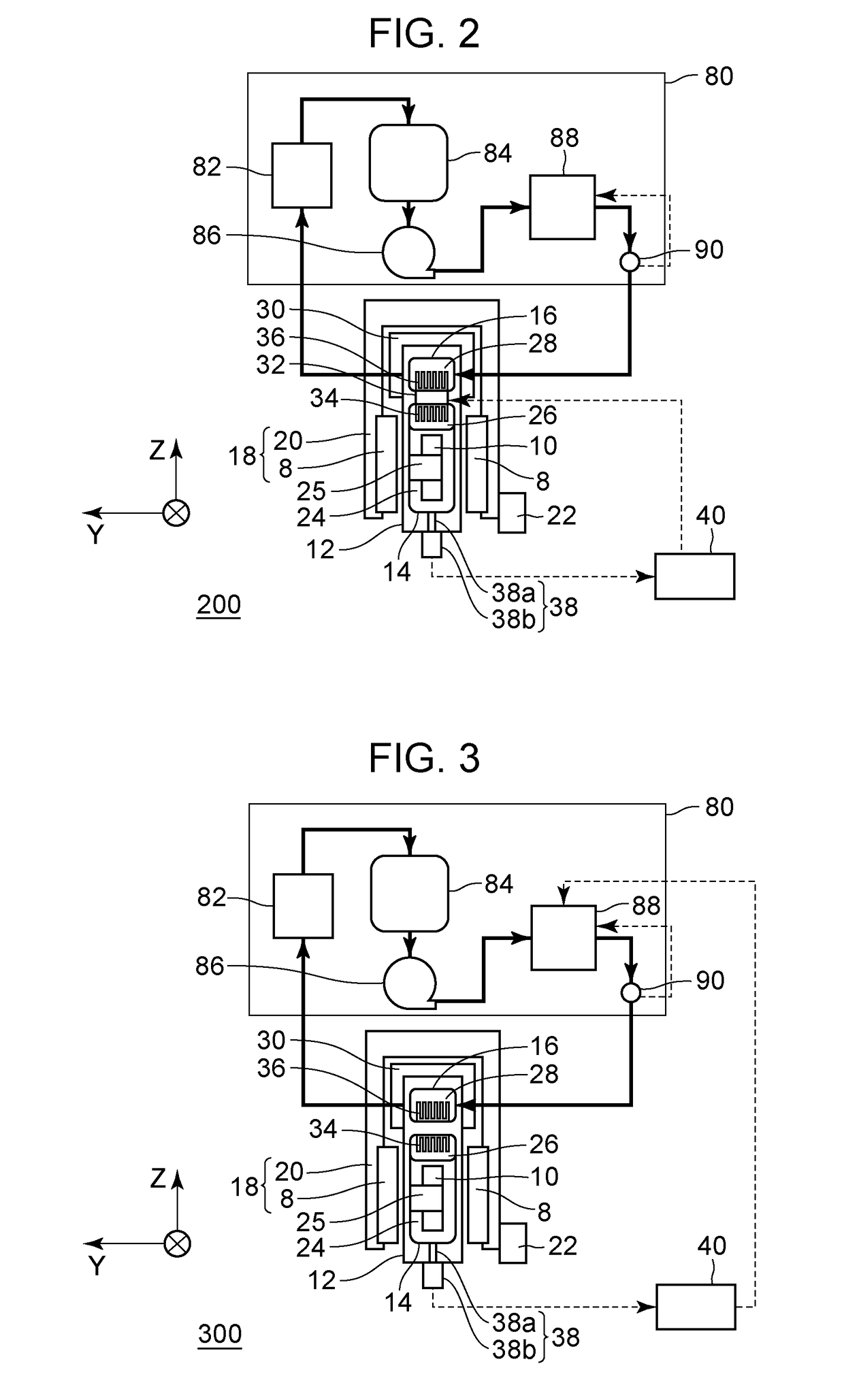
[0065]FIG. 3 illustrates a configuration of a drive unit 300 according to a second embodiment. A condensing means of the present embodiment also condenses the refrigerant 24 using the refrigerant 28 that flows through a system independent of the refrigerant 24. The drive unit 300 differs from the drive unit 200 in that as a regulating means, the drive unit 300 uses a temperature control means for controlling the temperature of the refrigerant 28, instead of the Peltier element 32. The other configurations of the drive unit 300 will not be described, as they are the same as those of the drive unit 200. Note that the heat exchanger 88 serves as the temperature control means in the circulating system 80.
[0066]A method for cooling the coil 10 in the drive unit 300 is as follows.
[0067]A pressure detected by the detecting means 38 is sent to the controller 40, which determines the temperature of the refrigerant 28 flowing inside the second housing 16. The controller 40 sets the determined...
third embodiment
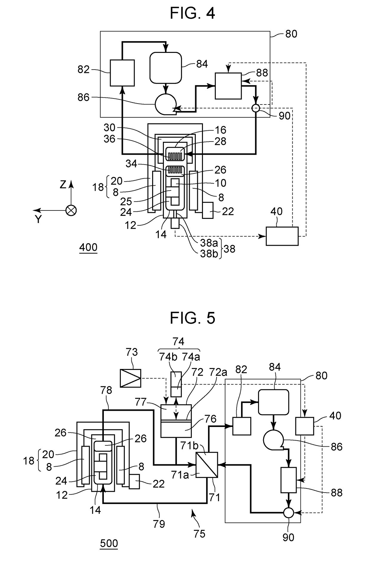
[0073]FIG. 4 illustrates a configuration of a drive unit 400 according to a third embodiment. A condensing means of the present embodiment also condenses the refrigerant 24 using the refrigerant 28 that flows through a system independent of the refrigerant 24. The drive unit 400 differs from the drive unit 300 in that as a regulating means, the drive unit 400 uses not only the heat exchanger 88 but also a flow rate control means for controlling the flow rate of the refrigerant 28. The other configurations of the drive unit 400 will not be described, as they are the same as those of the drive unit 300. Note that the pump 86 serves as the flow rate control means in the circulating system 80.
[0074]A method for cooling the coil 10 in the drive unit 400 is as follows.
[0075]A pressure detected by the detecting means 38 is sent to the controller 40, which determines the flow rate of the refrigerant 28 flowing inside the second housing 16. The controller 40 instructs the heat exchanger 88 t...
PUM
 Abstract
Description
Claims
Application Information
 - R&D Engineer
- R&D Manager
- IP Professional
- Industry Leading Data Capabilities
- Powerful AI technology
- Patent DNA Extraction
Browse by: Latest US Patents, China's latest patents, Technical Efficacy Thesaurus, Application Domain, Technology Topic.
© 2024 PatSnap. All rights reserved.Legal|Privacy policy|Modern Slavery Act Transparency Statement|Sitemap