Systems and methods for charging unmanned aerial vehicles on a moving platform

a technology for unmanned aerial vehicles and charging systems, applied in vehicle position/course/altitude control, process and machine control, instruments, etc., can solve the problems of high risk, high cost, and high cost of current inspection techniques, so as to reduce the risk associated, improve efficiency, and cost saving

Active Publication Date: 2018-12-20
AEROVIRONMENT INC
View PDF0 Cites 23 Cited by
  • Summary
  • Abstract
  • Description
  • Claims
  • Application Information

AI Technical Summary

Benefits of technology

[0007]In some cases, an unmanned USV-UAV team is designed to replace the need to deploy humans to inspect offshore energy production facilities, such as wind turbines. One benefit of the USV-UAV team is an improvement in the efficiency and reduction in the risk associated with inspections. The unmanned team also provides cost savings for both the turbine inspectors and the turbine operators, as well as of lower risk to humans that would otherwise be deployed to perform inspections.
[0008]In certain applications, the methods, devices, and systems described herein provide an unmanned team that can have many other advantages comparing with existing UAV-USV teams. These advantages includes but are not limited to: reduced inspection costs due to automating the inspection process with robots, more frequent inspections feasible due to lower cost to keep system deployed, improved safety and lower risk due to fewer deployed human inspectors, reduced repair costs due to persistent inspection, even in harsh environmental conditions, increased energy reliability by minimizing the minimizing the downtime of the wind turbine, or even continued operation during inspection.
[0009]Further, unmanned systems including UAVs present additional benefits over traditional human inspections. One benefit is the possibility for persistence, wherein the unmanned system can perform frequent and ongoing inspections, even in degraded environmental conditions that might prevent manned inspections. In further cases, with highly quality camera, for example, large format, high pixel density c

Problems solved by technology

However, current inspection techniques are expensive and dangerous, requiring humans to be deployed into the field, often into harsh offshore environments.
This process may take 6-8 hours per wind turbine, and involves a high level of risk.
This can significantly speed up the inspection process, and may only require 1.5 h

Method used


Image

  • Systems and methods for charging unmanned aerial vehicles on a moving platform
  • Systems and methods for charging unmanned aerial vehicles on a moving platform
  • Systems and methods for charging unmanned aerial vehicles on a moving platform

Examples


example 1

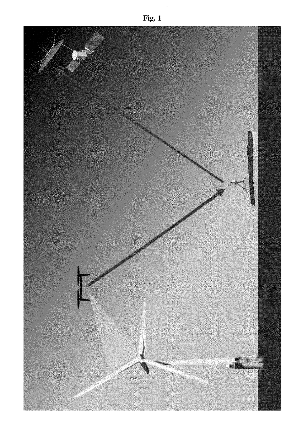
[0125]In a particular case, a UAV-USV team is deployed in an offshore wind farm. USV is pre-programmed with a route that transits to each turbine and pauses while the UAV inspects the turbine. When the USV reaches each turbine, the UAV autonomously launches from the USV. The UAV uses a pre-programmed flight pattern, together with active obstacle avoidance, to collect high resolution imagery of the entire wind turbine, from all sides, while the turbine is operating. Additional sensor data such as LIDAR and infrared (IR) could be included as well. The complete automated aerial inspection takes as little as 20 minutes. When the aerial inspection is complete, the UAV returns to the USV and executes an autonomous landing onto the USV deck. (Autonomous landings must be precise and reliable despite USV motion, wave action, and wind. Collected imagery is downloaded to the USV, stored, and transmitted to a remote user over SATCOM, 4G, or other means. Optionally, computer vision algorithms on...

example 2

[0126]A UAV-USV system is deployed in the North Sea to inspect offshore wind turbines. This is a harsh environment and risky to send people out. Furthermore, it is costly to shut down the wind turbines to conduct a manned inspection. When the UAV-USV system gets close to a wind turbine, the UAV launches from the USV and fly to close proximity of the turbine and capture high resolution images of it. During this process, the UAV's battery is depleted, so it returns to the USV and executes a precision landing on the charging platform. The USV begins to transit to the next wind turbine. Meanwhile, the charging platform is turned “on” and begins charging the UAV's batteries, via conduction or induction. When the battery is fully charged, the aircraft is ready to conduct another inspection, and the entire process starts anew.

example 3

[0127]Peacekeeping forces are deployed to a hostile area. Some of these troops are tasked with forward reconnaissance to ensure safe passage of a humanitarian aid convoy. These troops are inside an armored vehicle equipped with a drone on the roof. Before they enter a new area, the drone is launched from the roof of their moving vehicle and flies along their planned route, and provides live imagery to the peacekeeping troops in the vehicle. After the imagery is collected, the drone automatically returns to the moving vehicle and lands itself on a platform that rapidly recharges the batteries through conduction, without the need for a human to leave the security of the vehicle. The drone is then ready for its next flight as the troops enter a new hostile zone. In this scenario, it is plausible that the manned vehicle could be replaced with an unmanned ground vehicle.


PUM


Abstract

Disclosed herein are system and method for automatically recharging a unmanned aerial vehicle (UAV) on a moving platform, comprising: a software module identifying the moving platform; a software module estimating a real-time state of the moving platform; a software module controlling automatic landing of the UAV on the moving platform based on the real-time state estimation of the moving platform and data collected from the one or more sensors; a software module controlling automatic connection of the UAV to a charging station of the moving platform with a pre-determined orientation; and a software module controlling automatic taking off of the UAV from the moving platform after charging.

Description

CROSS-REFERENCE[0001]This application claims the benefit of U.S. Provisional Patent Application No. 62 / 522,563 filed Jun. 20, 2017, and U.S. Provisional Patent Application No. 62 / 556,044 filed Sep. 8, 2017, each of which are incorporated here in by reference in its entirety.BACKGROUND OF THE INVENTION[0002]Robots are machines that are typically programmable by a computer and are capable of carrying out a complex series of actions. Unmanned aerial vehicles (UAVs) are certain types of robotic devices that can be used for performing surveillance, reconnaissance, and exploration tasks for military and civilian applications.SUMMARY OF THE INVENTION[0003]Offshore energy production assets, especially wind turbines, are being increasingly installed and operated, and are a rapidly growing source of energy in many countries throughout the world. Offshore energy production assets require frequent detailed inspection to ensure the ongoing health, safety, and financial viability of the asset. Ho...

Claims


Application Information

Patent Timeline
IPC IPC(8): G05D1/06G05D1/00B64C39/02G08G5/00G08G5/02G06K9/00
CPCG05D1/0684G05D1/0088G05D1/0661B64C39/024G08G5/0073G08G5/025G06K9/00624B64C2201/066B64C2201/141G08G5/0021G08G5/0069G06V20/176G06V10/245G06V20/17B64U50/34B64U2201/10
Inventor COLLINS, GAEMUSCLAUSSE, AUBREYTWINING, DAVID
Owner AEROVIRONMENT INC
Why Eureka
Try Eureka