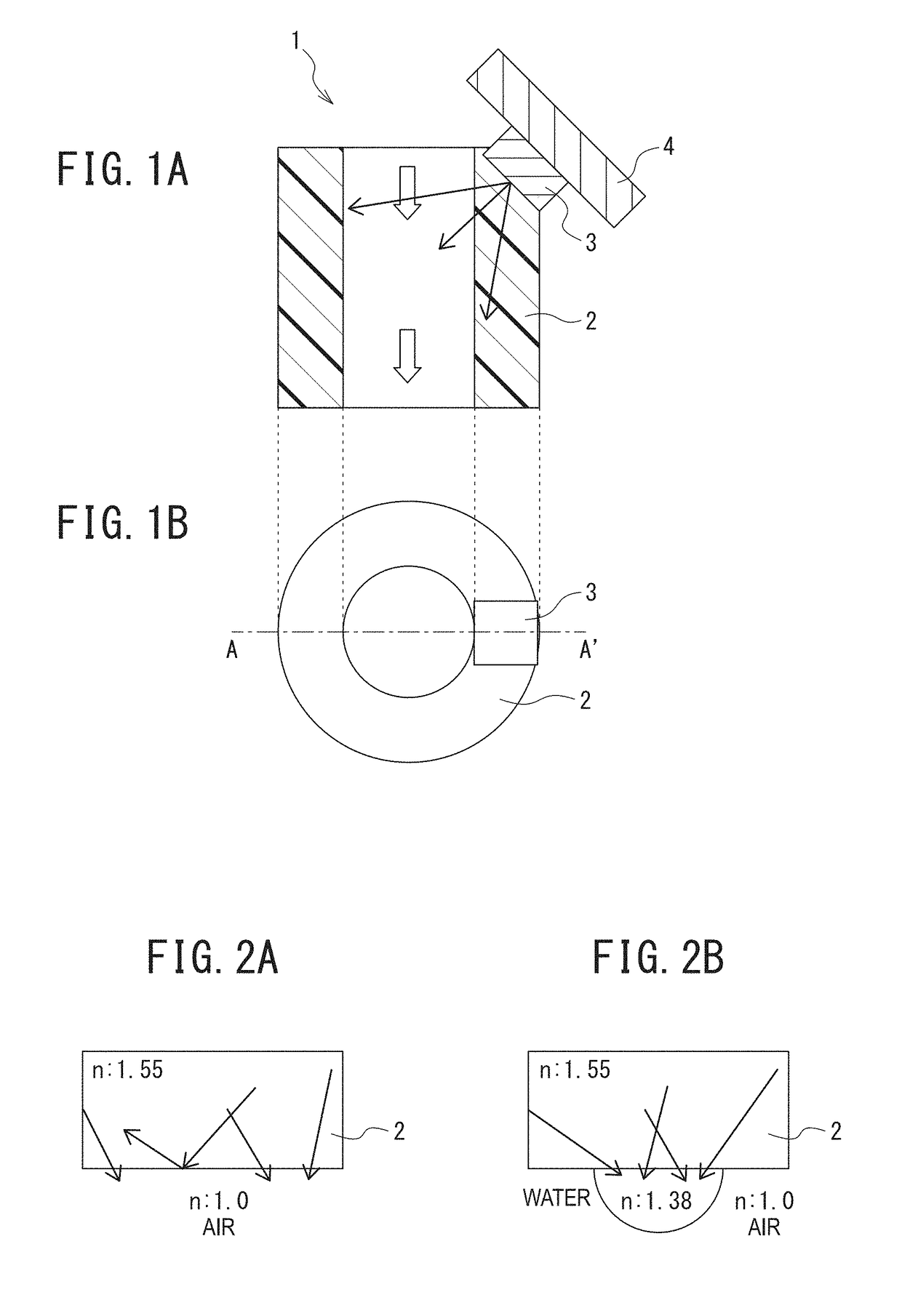
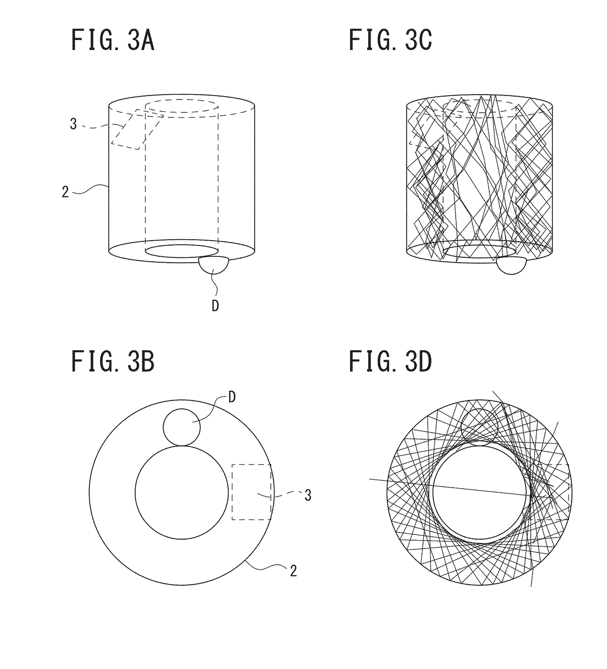
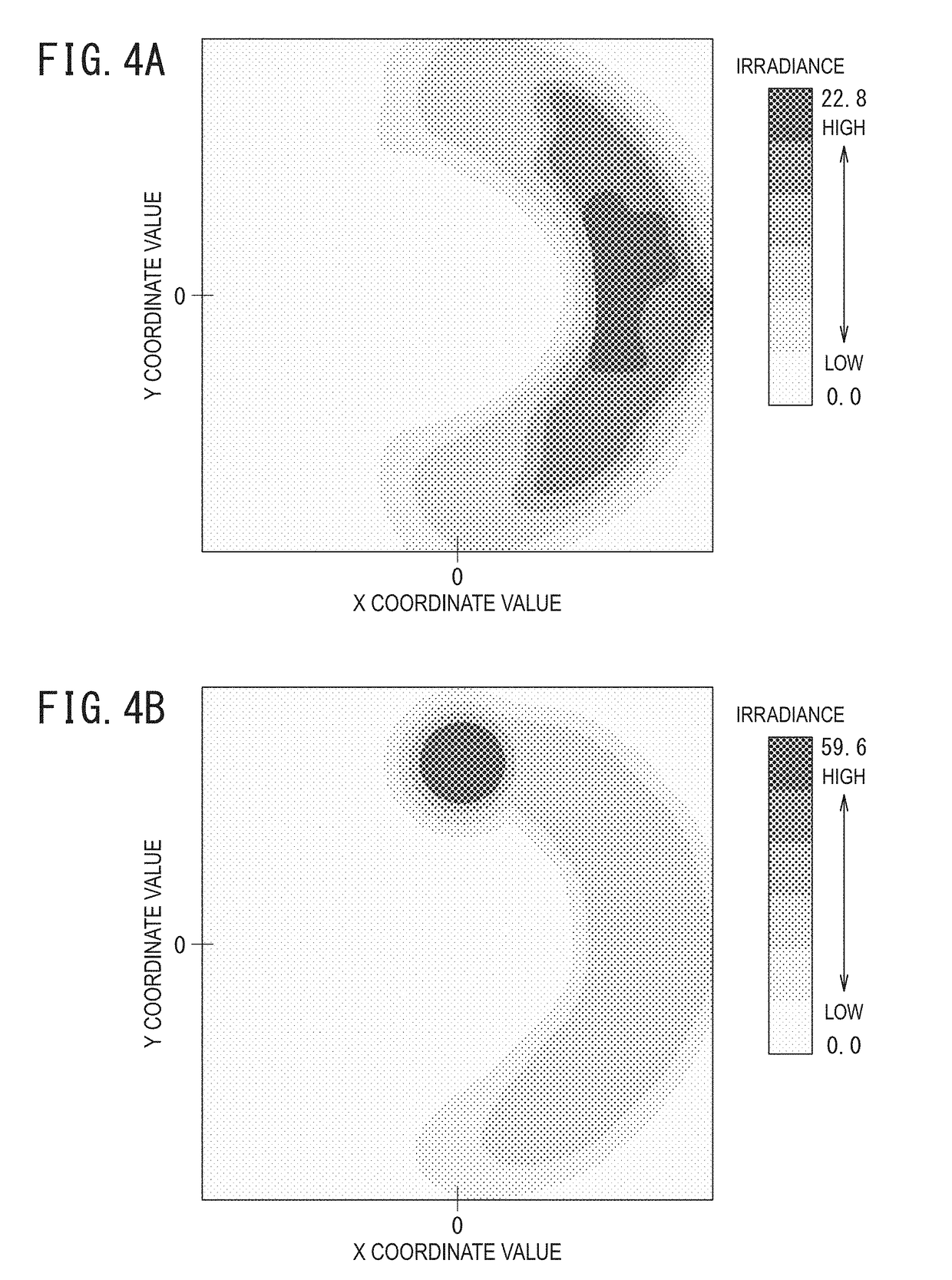
Sterilizer, supply device, and sterilization method

a technology of supply device and sterilizer, which is applied in the direction of disinfection, specific water treatment objectives, chemistry apparatus and processes, etc., can solve the problems of insufficient ultraviolet rays reaching a the shape design of the water supply device is limited, and the amount of ultraviolet rays reaching the portion to be sterilized is not sufficient, so as to prevent the propagation of bacteria, reduce the size of the sterilizer, and the design is free. freedom

Active Publication Date: 2018-12-27
ASAHI KASEI KK
View PDF3 Cites 4 Cited by
  • Summary
  • Abstract
  • Description
  • Claims
  • Application Information

AI Technical Summary

Benefits of technology

The present invention provides a sterilizer that prevents the absorption of ultraviolet rays near the discharge port of drinking water or other liquids, allowing for more effective sterilization without being limited by the positioning of the ultraviolet-ray light source. Additionally, the invention includes a device and method for supplying drinking water or other liquids that utilizes the sterilizer. This results in better light gathering and sterilization with greater design flexibility.

Problems solved by technology

Therefore, there is a problem that the arrangement positional relationship therebetween causes limitations of the shape design of the water supply device or an increase in the size of the water supply device, e.g., a water outlet portion is not curved to be easily irradiated with light, a large number of light sources need to be disposed to be able to irradiate the entire region contacting water of the water outlet portion, and the like.
However, in this case, the amount of the ultraviolet rays reaching a portion to be sterilized has not been sufficient because the ultraviolet rays are absorbed by a member configuring the water outlet body or the ultraviolet rays are reflected on the interface between air and the water outlet body.
Or, in order to achieve a sufficient amount of ultraviolet rays in sterilizing, the light source itself needs to be made more powerful but an increase in the output of the light source presents a new problem in terms of design of inducing consideration to a degradation or the like of a water supply device constituent member by the ultraviolet rays.

Method used


Image

  • Sterilizer, supply device, and sterilization method
  • Sterilizer, supply device, and sterilization method
  • Sterilizer, supply device, and sterilization method

Examples


Embodiment Construction

[0030]Next, one embodiment of the present invention is described with reference to the drawings. In the following description of the drawings, the same or similar portions are designated by the same or similar reference numerals. However, it should be noted that the drawings are schematically illustrated and the relationship between the thickness and the plane dimension and the ratio of the thickness of each layer are different from the actual relationship and ratio. Therefore, a specific thickness or dimension should be determined considering the following description. Moreover, it is a matter of course that portions where the mutual relationships or the ratios of dimensions are different from each other between the drawings are included.

[0031]Moreover, the embodiments described below describe examples of a device or a method for crystalizing the technical idea of the present invention and the technical idea of the present invention does not specify materials, shapes, structures, a...


PUM

PropertyMeasurementUnit
center wavelengthaaaaaaaaaa
optical refractive indexaaaaaaaaaa

Abstract

To provide a sterilizer preventing ultraviolet ray absorption in a body of a case body and emitting ultraviolet rays to a portion to be sterilized without involving positioning with high accuracy.A sterilizer 1a has a case body 2 containing a member having an ultraviolet-ray transmission property and a flow passage formed thereinside and an ultraviolet-ray irradiation portion 3 irradiating a predetermined portion of a member configuring the case body 2 with ultraviolet rays, in which ultraviolet rays emitted from the ultraviolet-ray irradiation portion 3 travel in a body of the case body 2 to be radiated at least from an end surface on an output end side of the case body 2.

Description

BACKGROUND OF THE INVENTIONField of the Invention[0001]The present invention relates to a sterilizer, a supply device supply including the sterilizer, and a sterilization method.Description of the Related Art[0002]In recent years, there are water supply devices, such as a water server configured to store drinking water, such as RO (Reverse Osmosis) water or mineral water, in a water storage tank and supply the stored drinking water by a user's cock operation or button operation for drinking. In water storage portions of the water supply devices, a mechanism of cooling or heating water to enable easy supply of cold water or hot water is added in many cases.[0003]In such water supply devices, a mechanism of suppressing the development and proliferation of bacteria, i.e., a sterilization mechanism, has been introduced in many cases. In the example of the water server, the water itself delivered with a bottle is basically sterilized, and therefore the sterilization is performed for the ...

Claims


Application Information

Patent Timeline
Patent Type & Authority Applications(United States)
IPC IPC(8): C02F1/32A61L2/10C02F1/28C02F1/22
CPCC02F1/32A61L2/10C02F1/28C02F1/22C02F2201/3228C02F2201/3222A61L2202/11C02F1/325C02F2303/04C02F1/006A61L2202/23
Inventor KISHI, HIROYUKISUGIYAMA, SHOMIYA, SHINJI
Owner ASAHI KASEI KK
Why Eureka
Try Eureka