
Abradable coating having variable densities

a technology of abradable coating and densities, which is applied in the direction of turbines, machines/engines, mechanical equipment, etc., can solve the problems of reducing the performance of turbines, increasing the leakage rate past the tips of blades, and premature erosion of conventional abradable tracks, so as to achieve easy abradability

Active Publication Date: 2018-12-27
SN DETUDE & DE CONSTR DE MOTEURS DAVIATION S N E C M A
View PDF9 Cites 5 Cited by
  • Summary
  • Abstract
  • Description
  • Claims
  • Application Information

AI Technical Summary

Benefits of technology

The patent describes a method to create a coating with different densities on a substrate. By adjusting various parameters, such as the size and porosity of precursor materials, the final porosity of the coating can be achieved. This results in an abridable coating that is easily abraced in areas that come into contact with a moving body, while protecting sensitive zones from erosion. The technical effects of the patent are the creation of a coating with varying densities that improves performance and reliability of components in high-speed applications.

Problems solved by technology

Specifically, the burnt gas from the combustion chamber penetrates into the high pressure turbine at temperature and pressure levels that are very high, thereby leading to premature erosion of conventional abradable tracks.
Nevertheless, it can naturally be understood that under such circumstances, the integrity of the blades is no longer ensured in the event of contact with the stator, which means that it is necessary to provide greater clearance between the rotor and the stator, thereby increasing the rate of leakage past the tips of the blades and thus reducing the performance of the turbine.

Method used


Image

  • Abradable coating having variable densities
  • Abradable coating having variable densities
  • Abradable coating having variable densities

Examples


Embodiment Construction

)

[0062]In order to make the invention more concrete, examples of methods and abradable tracks are described below in detail with reference to the accompanying drawings. It should be recalled that the invention is not limited to these examples.

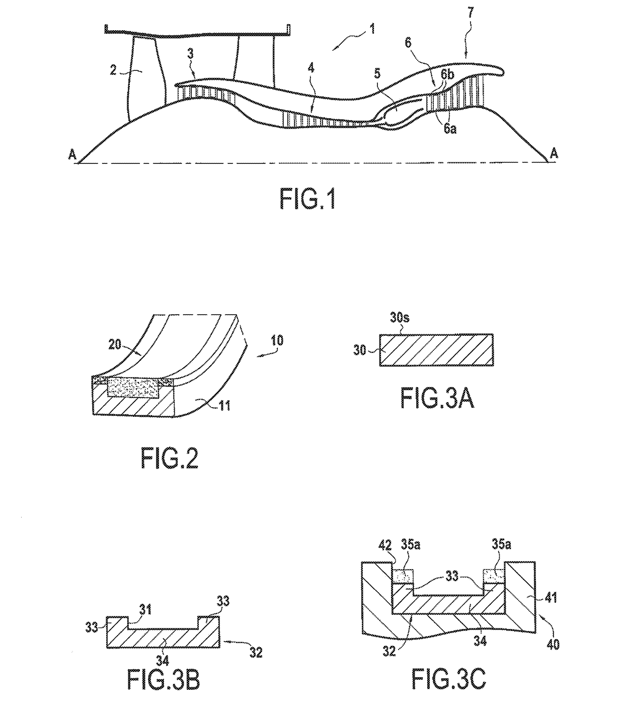
[0063]FIG. 1 is a section view of a bypass turbojet 1 of the invention, the section being on a vertical plane containing the main axis A of the turbojet. Going from upstream to downstream in the air stream flow direction, the turbojet comprises: a fan 2; a low pressure compressor 3; a high pressure compressor 4; a combustion chamber 5; a high pressure turbine 6; and a low pressure turbine 7.

[0064]The high pressure turbine 6 has a plurality of blades 6a rotating with the rotor and a plurality of guide vanes 6b mounted on the stator. The stator of the turbine 6 comprises a plurality of stator rings 10 arranged facing the movable blades 6a of the turbine 6. As can be seen in FIG. 2, each stator ring 10 is subdivided into a plurality of sectors 11,...


PUM

PropertyMeasurementUnit
porosityaaaaaaaaaa
porosityaaaaaaaaaa
grain sizeaaaaaaaaaa

Abstract

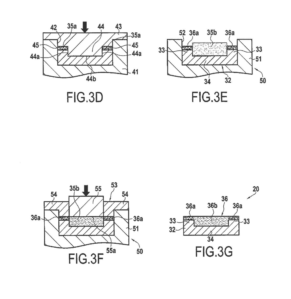
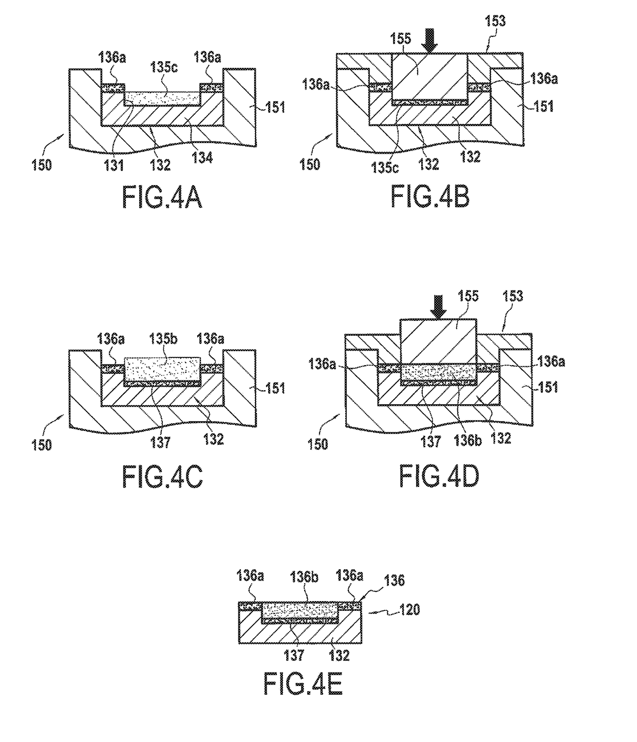
A method of fabricating an abradable coating of varying density, and an abradable coating of varying density. The method comprises the following steps: providing a substrate having a first portion and a second portion; depositing a first precursor material on the first portion of the substrate compressing the first precursor material between the substrate and a first bearing surface; sintering the first precursor material as compressed in this way in order to obtain a first abradable coating portion on the first portion of the substrate, and possessing a first density; depositing a second precursor material on the second portion of the substrate; and compressing the second precursor material between the substrate and a second bearing surface.

Description

FIELD OF THE INVENTION[0001]The present disclosure relates to a method of fabricating an abradable coating of varying density, and also to such an abradable coating of varying density.[0002]Such an abradable coating may be used in particular for fitting to a ring of a rotary machine so as to provide the machine with sealing at the tips of rotating blades, for example. Such an abradable coating is particularly adapted for fitting to turbine rings in the field of aviation, and most particularly in airplane turbojets.STATE OF THE PRIOR ART[0003]In numerous rotary machines, it is now the practice to provide the stator ring with abradable tracks facing the tips of blades of the rotor. Such tracks are made using so-called “abradable” materials that, on coming into contact with the rotating blades, wear more easily than the blades. This ensures minimal clearance between the rotor and the stator, thereby improving the performance of the rotary machine, without running the risk of damaging t...

Claims


Application Information

Patent Timeline
Patent Type & Authority Applications(United States)
IPC IPC(8): F01D11/12B22F3/105B22F5/00B22F7/02
CPCB22F3/105B22F7/06C23C24/08F01D11/12B22F2998/10F01D11/122B22F5/009F05B2230/90B22F3/02B22F3/10B22F7/02F05D2230/22F05D2230/30F05D2300/514F05D2300/522F05D2300/609
Inventor LE BIEZ, PHILIPPE CHARLES ALAIN
Owner SN DETUDE & DE CONSTR DE MOTEURS DAVIATION S N E C M A
Learn More