Magnetic resonance coil arrangement with adaptive coil spacing layer

a magnetic resonance and coil arrangement technology, applied in the field of coil arrangement for a magnetic resonance imaging system, can solve the problems of affecting the image quality, affecting the quality of the image, and affecting the accuracy of the image, so as to avoid slippage of the two layers, avoid time-consuming and labor-intensive assembly, and reduce the effect of overlapping

Active Publication Date: 2018-12-27
SIEMENS HEALTHCARE GMBH
View PDF2 Cites 5 Cited by
  • Summary
  • Abstract
  • Description
  • Claims
  • Application Information

AI Technical Summary

Benefits of technology

[0012]It is the object of the disclosure to provide a local coil that achieves improved imaging results with different patients or different regions of a patient's body.
[0028]In one possible embodiment of the coil arrangement, the vertical plug-in connection elements are configured to connect the coil spacing layer to an outer layer and / or a second coil spacing layer. Advantageously, the outer layer may be fixed on the spacing layer thus enabling the avoidance of slippage of the two layers against each other or unwanted detachment of the outer layer from the spacing layer.

Problems solved by technology

However, image quality may be degraded in the case of patients with small heads because the antenna structures are not optimally close to the anatomy.
Flexible coil structures may compensate lack of adaptation, but a conventional problem is that such arrangements also only enable three-dimensional conversions to a restricted extent.
This results in bulging and the protrusion of sub-regions of the coil arrangement.
As a result, the image quality achieved is not optimum.

Method used


Image

  • Magnetic resonance coil arrangement with adaptive coil spacing layer
  • Magnetic resonance coil arrangement with adaptive coil spacing layer
  • Magnetic resonance coil arrangement with adaptive coil spacing layer

Examples


Embodiment Construction

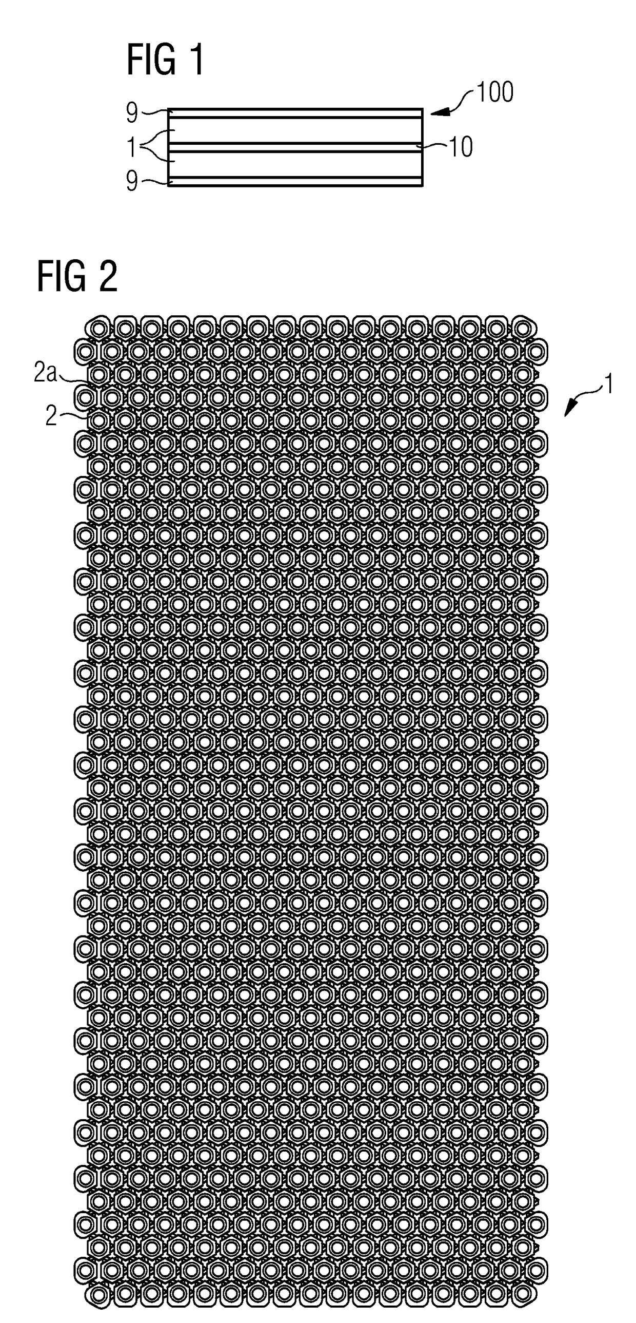
[0046]FIG. 1 is a schematic cross-sectional representation of a section of a coil arrangement 100, which is used as a local coil for detecting magnetic-resonance signals. The section has a sandwich structure and includes in its interior a coil layer 10 including a plurality of coil loops in a two-dimensional or laminar arrangement. The coil layer 10 is surrounded on each of its two sides by a spacing layer 1. The spacing layers 1 are each about 5 mm thick and are configured to provide a safety distance between an examination object, (e.g., a patient), and the coil layer 10 and between the coil layer 10 and the outside world, (e.g., the medical staff). Outer layers 9 are applied to each of the outward-facing sides 9 of spacing layers 1 as protective layers.

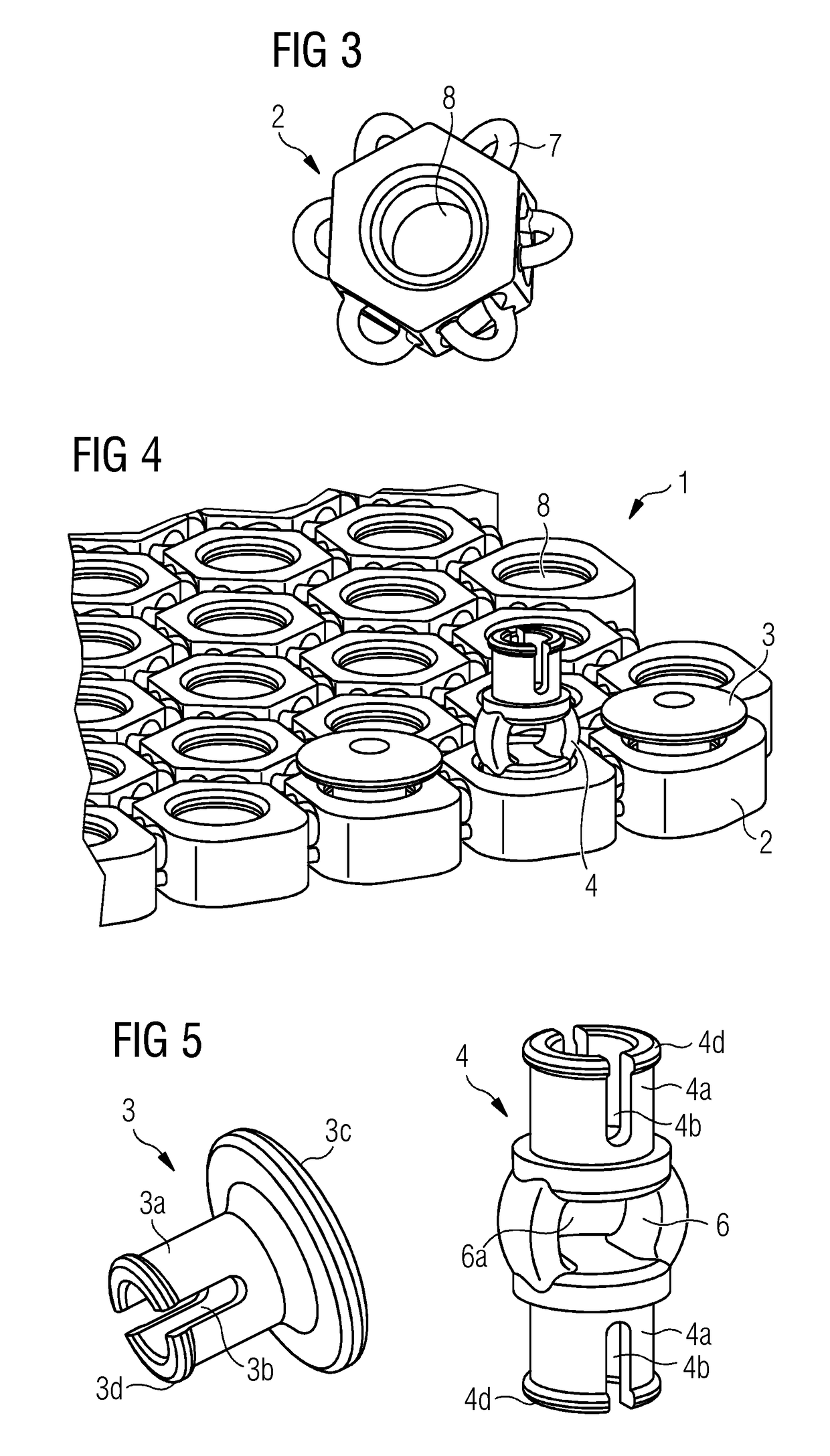
[0047]FIG. 2 is a top view of a spacing layer 1 of a local coil matrix with a plurality of perforated components 2. The individual components 2 are connected to one another via flexible connections 2a in a network structure and are...


PUM


Abstract

A coil arrangement for a magnetic resonance scanner with at least one coil spacing layer including a two-dimensional matrix with a flexible, network structure is described. The two-dimensional matrix has a plurality of flexibly interlinked substructures. A method for producing a coil arrangement is also described. Also described is a magnetic resonance imaging system.

Description

[0001]The application claims the benefit of German Patent Application No. DE 10 2017 210 422.8, filed Jun. 21, 2017, which is hereby incorporated by reference in its entirety.TECHNICAL FIELD[0002]The disclosure relates to a coil arrangement for a magnetic resonance imaging system. The disclosure furthermore relates to a method for producing such a coil arrangement. The disclosure also relates to a magnetic resonance imaging system.BACKGROUND[0003]Magnetic resonance scanners are imaging devices that, for mapping an examination object, align nuclear spins of the examination object with a strong external magnetic field and excite the nuclear spins to precession around this alignment via a magnetic alternating field. The precession or return of the spins from this excited state into a state with lower energy in turn generates in response a magnetic alternating field, also known as a magnetic resonance signal, which is received by antennas.[0004]By magnetic gradient fields, spatial encod...

Claims


Application Information

Patent Timeline
Patent Type & Authority Applications(United States)
IPC IPC(8): G01R33/3415G01R33/34
CPCG01R33/3415G01R33/34084G01R33/34007A61B5/055G01R33/341
Inventor CANDIDUS, YVONNEZINK, STEPHAN
Owner SIEMENS HEALTHCARE GMBH
Why Eureka
Try Eureka