Lithography model for three-dimensional patterning device

a three-dimensional patterning and lithography technology, applied in the direction of optical devices, photomechanical devices, instruments, etc., can solve the problems of large cost of making high-end patterning devices, application of opcs is generally not possible,

Active Publication Date: 2019-07-23
ASML NETHERLANDS BV
View PDF26 Cites 0 Cited by
  • Summary
  • Abstract
  • Description
  • Claims
  • Application Information

AI Technical Summary

Benefits of technology

[0009]Application of model-based OPC to a target design involves good process models and considerable computational resources, given the many millions of features typically present in a chip design. However, applying OPC is generally not an “exact science”, but an empirical, iterative process that does not always compensate for all possible proximity effect. Therefore, effect of OPC, e.g., design layouts after application of OPC and any other RET, need to be verified by design inspection, i.e. intensive full-chip simulation using calibrated numerical process models, in order to minimize the possibility of design flaws being built into the patterning device pattern. This is driven by the enormous cost of making high-end patterning devices, which run in the multi-million dollar range, as well as by the impact on turn-around time by reworking or repairing actual patterning devices once they have been manufactured.
[0012]In addition to optimization to design layouts or patterning devices (e.g., OPC), the illumination source can also be optimized, either jointly with patterning device optimization or separately, in an effort to improve the overall lithography fidelity. The terms “illumination source” and “source” are used interchangeably in this document. Since the 1990s, many off-axis illumination sources, such as annular, quadrupole, and dipole, have been introduced, and have provided more freedom for OPC design, thereby improving the imaging results, As is known, off-axis illumination is a proven way to resolve fine structures (i.e., target features) contained in the patterning device. However, when compared to a traditional illumination source, an off-axis illumination source usually provides less radiation intensity for the aerial image (AI). Thus, it becomes desirable to attempt to optimize the illumination source to achieve the optimal balance between finer resolution and reduced radiation intensity.
[0015]Relatedly, the pressure of ever decreasing design rules have driven semiconductor chipmakers to move deeper into the low k1 lithography era with existing 193 nm ArF lithography. Lithography towards lower k1 puts heavy demands on RET, exposure tools, and the need for litho-friendly design. 1.35 ArF hyper numerical aperture (NA) exposure tools may be used in the future. To help ensure that circuit design can be produced on to the substrate with workable process window, source-patterning device optimization (referred to herein as source-mask optimization or SMO) is becoming a significant RET for 2× nm node.

Problems solved by technology

However, applying OPC is generally not an “exact science”, but an empirical, iterative process that does not always compensate for all possible proximity effect.
This is driven by the enormous cost of making high-end patterning devices, which run in the multi-million dollar range, as well as by the impact on turn-around time by reworking or repairing actual patterning devices once they have been manufactured.

Method used


Image

  • Lithography model for three-dimensional patterning device
  • Lithography model for three-dimensional patterning device
  • Lithography model for three-dimensional patterning device

Examples


Embodiment Construction

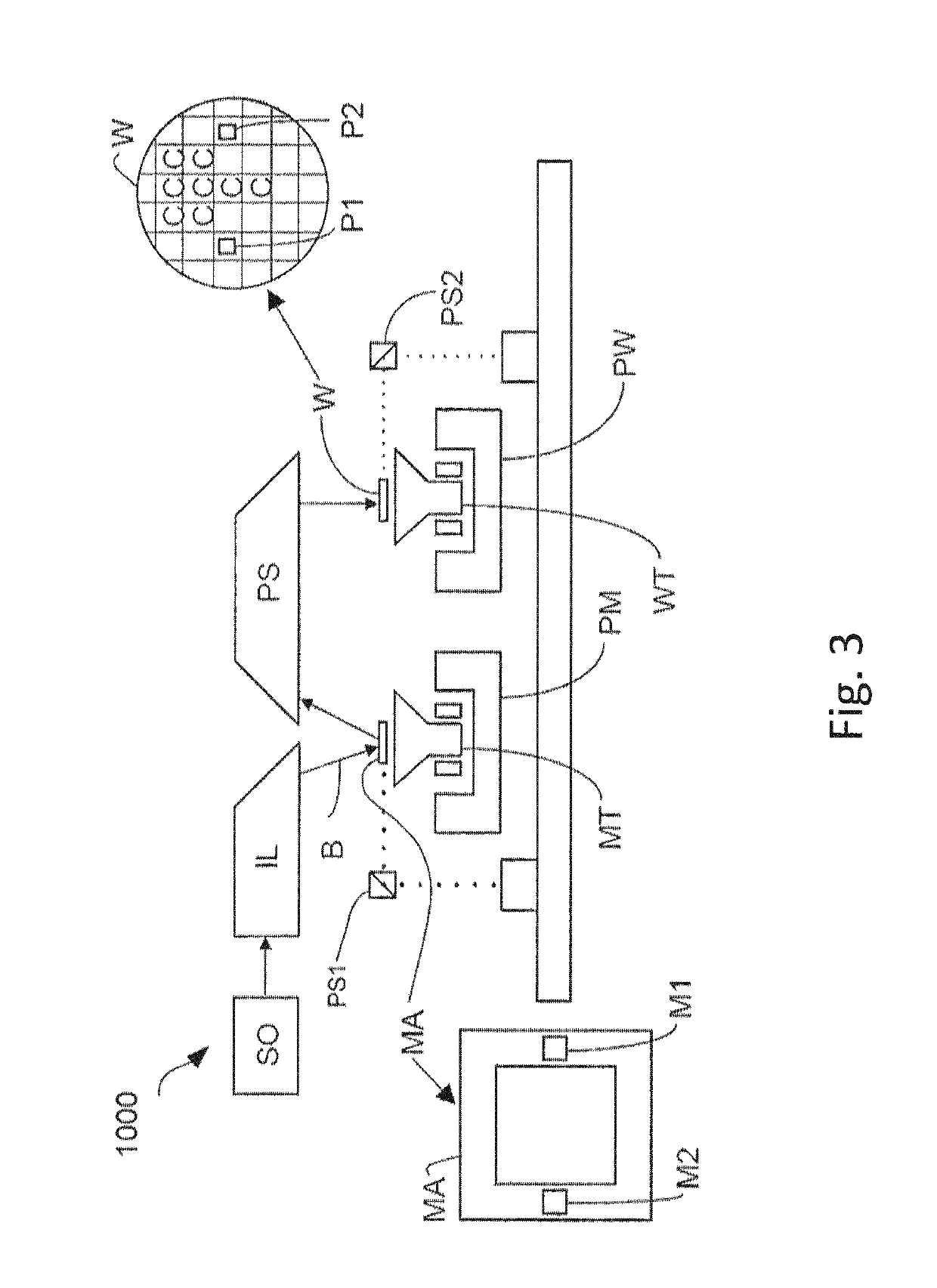
[0055]Although specific reference may be made in this text to the manufacture of ICs, it should be explicitly understood that the description herein has many other possible applications. For example, it may be employed in the manufacture of integrated optical systems, guidance and detection patterns for magnetic domain memories, liquid-crystal display panels, thin-film magnetic heads, etc. The skilled artisan will appreciate that, in the context of such alternative applications, any use of the terms “reticle”, “wafer” or “die” in this text should be considered as interchangeable with the more general terms “mask”, “substrate” and “target portion”, respectively.

[0056]In the present document, the terms “radiation” and “beam” are used to encompass all types of electromagnetic radiation, including ultraviolet radiation (e.g. with a wavelength of 365, 248, 193, 157 or 126 nm) and EUV (extreme ultra-violet radiation, e.g. having a wavelength in the range 5-20 nm).

[0057]The term “optimizin...


PUM

PropertyMeasurementUnit
wavelengthaaaaaaaaaa
diameteraaaaaaaaaa

Abstract

A computer-implemented method for simulating a scattered radiation field of a patterning device including one or more features, in a lithographic projection apparatus, the method including: determining a scattering function of the patterning device using one or more scattering functions of feature elements of the one or more features; wherein at least one of the one or more features is a three-dimensional feature, or the one or more scattering functions characterize scattering of incident radiation fields at a plurality of incident angles on the feature elements.

Description

CROSS-REFERENCE TO RELATED APPLICATIONS[0001]This application is the U.S. national phase entry of PCT patent application no. PCT / EP2014 / 052109, which was filed on Feb. 4, 2014, which claims the benefit of priority of U.S. provisional application no. 61 / 768,228, which was filed on Feb. 22, 2013, and which is incorporated herein in its entirety by reference.BACKGROUND[0002]A lithographic projection apparatus can be used, for example, in the manufacture of integrated circuits (ICs). In such a case, a patterning device (e.g., a mask) may contain or provide a circuit pattern corresponding to at least a part of an individual layer of the IC (“design layout”), and this circuit pattern can be transferred onto a target portion (e.g. comprising one or more dies) on a substrate (e.g., silicon wafer) that has been coated with a layer of radiation-sensitive material (“resist”), by methods such as irradiating the target portion through the circuit pattern on the patterning device. In general, a s...

Claims


Application Information

Patent Timeline
Patent Type & Authority Patents(United States)
IPC IPC(8): G03F7/20
CPCG03F7/7055G03F7/70441G03F7/705
Inventor LIU, PENG
Owner ASML NETHERLANDS BV
Why Eureka
Try Eureka