Pressure Sensor System

a sensor system and pressure sensor technology, applied in the direction of machines/engines, process and machine control, instruments, etc., can solve the problems of inability to accurately measure, high cost of special-use pressure sensors, and inability to meet the needs of general-use applications, etc., to achieve accurate measurement and good ultraviolet ray transmission

Inactive Publication Date: 2019-01-03
WESTMORELAND III AUBREY DARE
View PDF0 Cites 5 Cited by
  • Summary
  • Abstract
  • Description
  • Claims
  • Application Information

AI Technical Summary

Benefits of technology

[0013]The present invention is directed to in situ monitoring of low pressure, hazardous chemicals. A pressure sensor system is presented for accurately measuring low and ultra-low pressures. A sealed pressure bladder is formed from a pliable, yet chemically resistant material fluoropolymer, such as FEP (fluorinated ethylene propylene) or PFA (perfluoroalkoxy polymer sometimes referred to improperly as MFA). FEP has a working temperature of between −100° F. and 400° F., is chemically inert, a good transmitter of ultraviolet rays and, importantly, chemical and corrosion resistance. The texture of FEP fluoropolymer ranges between somewhat pliable to very soft and, therefore, may need additional structural support in certain applications. The pressure bladder is filled with an inert, non-reactive, stable fluid and is hydraulically coupled to a pressure sensor for measuring pressure. The fluid fills the pressure bladder and a measurement chamber of the pressure sensor. The pressure bladder is immersed in a fluid medium contained in a reservoir for monitoring the pressure of the fluid medium. Optimally, the pressure sensor's electronics are hydraulically isolated from the fluid medium and the hydraulic pressure of the reservoir. The pressure sensor is electrically connected to external electrical conductors that provide an electrical connection to electrical monitoring / processing equipment for powering the sensor and receiving its output signals. This bladder configuration insulates the internal components of the pressure sensor from the fluid medium contained in the reservoir, in so doing is particularly useful for monitoring the pressure of hazardous mediums.
[0014]In accordance with one exemplary embodiment of the present invention, the pressure bladder forms substantially cylindrically shaped interior chamber having a closed distal end and an open proximate end. The open end of the cylindrically shaped interior chamber is hydraulically coupled to a substantially cylindrically shaped support mandrel with a second substantially cylindrically shaped interior chamber. The second substantially cylindrically shaped interior chamber has a smaller diameter than the bladder and the walls of the mandrel are much thicker, thereby forming a more rigid cylinder. The capillary tube provides a hydraulic path for the fluid that transmits pressures between the pressure bladder and sensor.
[0015]The support mandrel serves three purposes: it provides the rigidity necessary for securing a hydraulic fitting for isolating the sensor from the reservoir; it provides a path between the pressure bladder and sensor for communicating pressures; and it provides a structure for mechanically coupling the sensor. Fluoropolymer materials lend themselves to various economical fabrication techniques. Fluoropolymer rods can be easily drilled and shaped. They form good hydraulic coupling with other types of plastic, metals and ceramics. Fluoropolymer materials can be permanently jointed together. Most fluoropolymers, including PTFE, FEP, PFA or ETFE, can be welded and FEP welds form secure, strong and waterproof joints.

Problems solved by technology

Deflection-type pressure sensors are highly accurate and produced in quantity, fairly inexpensive, however, as they utilize multiple moving parts, are prone to wear and ultimately, failure.
While both deflection-type and piezoelectric-type pressure devices have been extremely successful, their acceptance has largely been limited to general use applications.
Conversely, special-use pressure sensors are sometimes extraordinarily expensive.
Importantly, the current per-unit cost for low pressure sensors for hazardous application is nearly equal to the cost of the chemical injection tank itself.

Method used


Image

  • Pressure Sensor System
  • Pressure Sensor System
  • Pressure Sensor System

Examples


Embodiment Construction

Element Reference Number Designations

[0048]

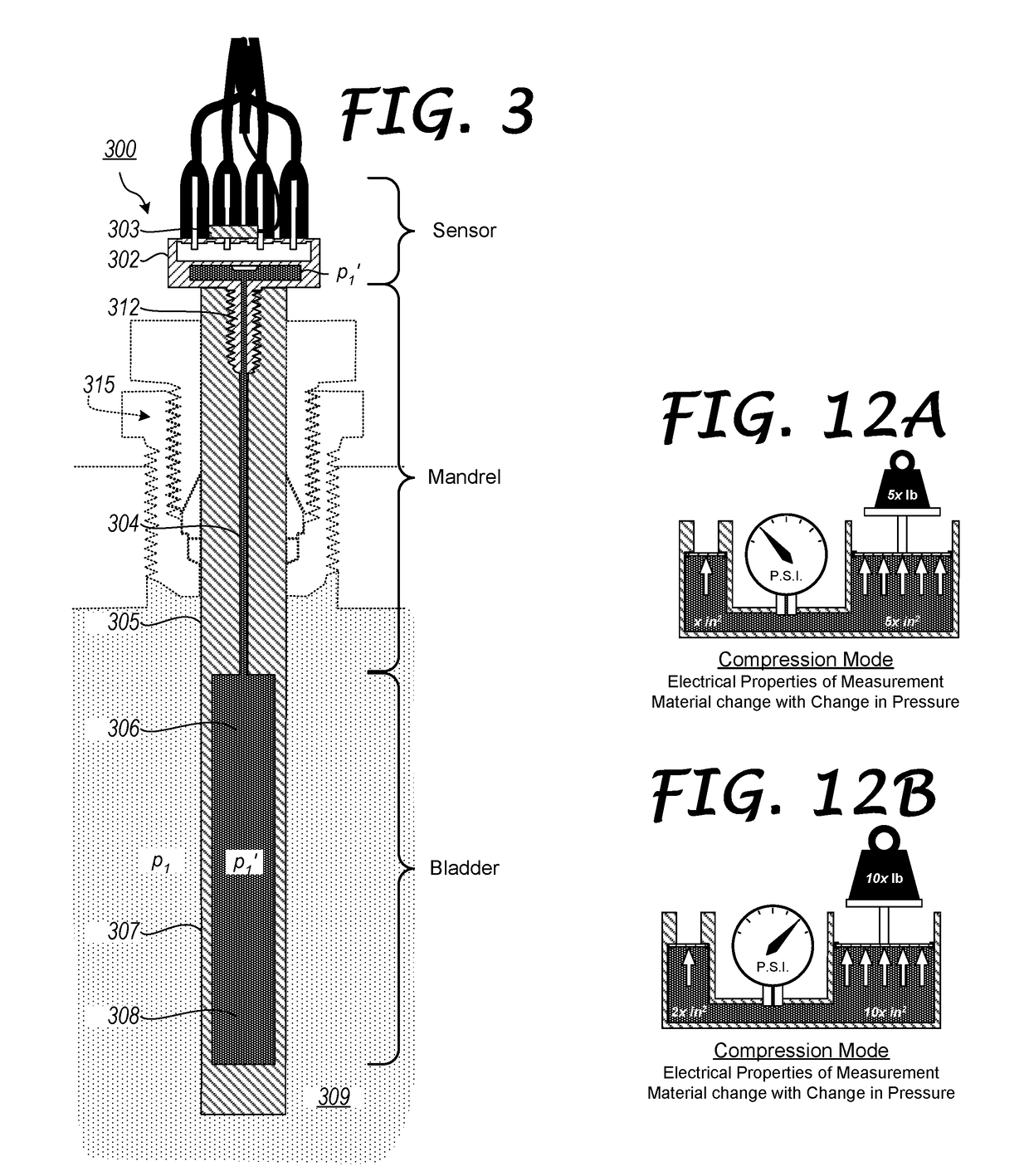
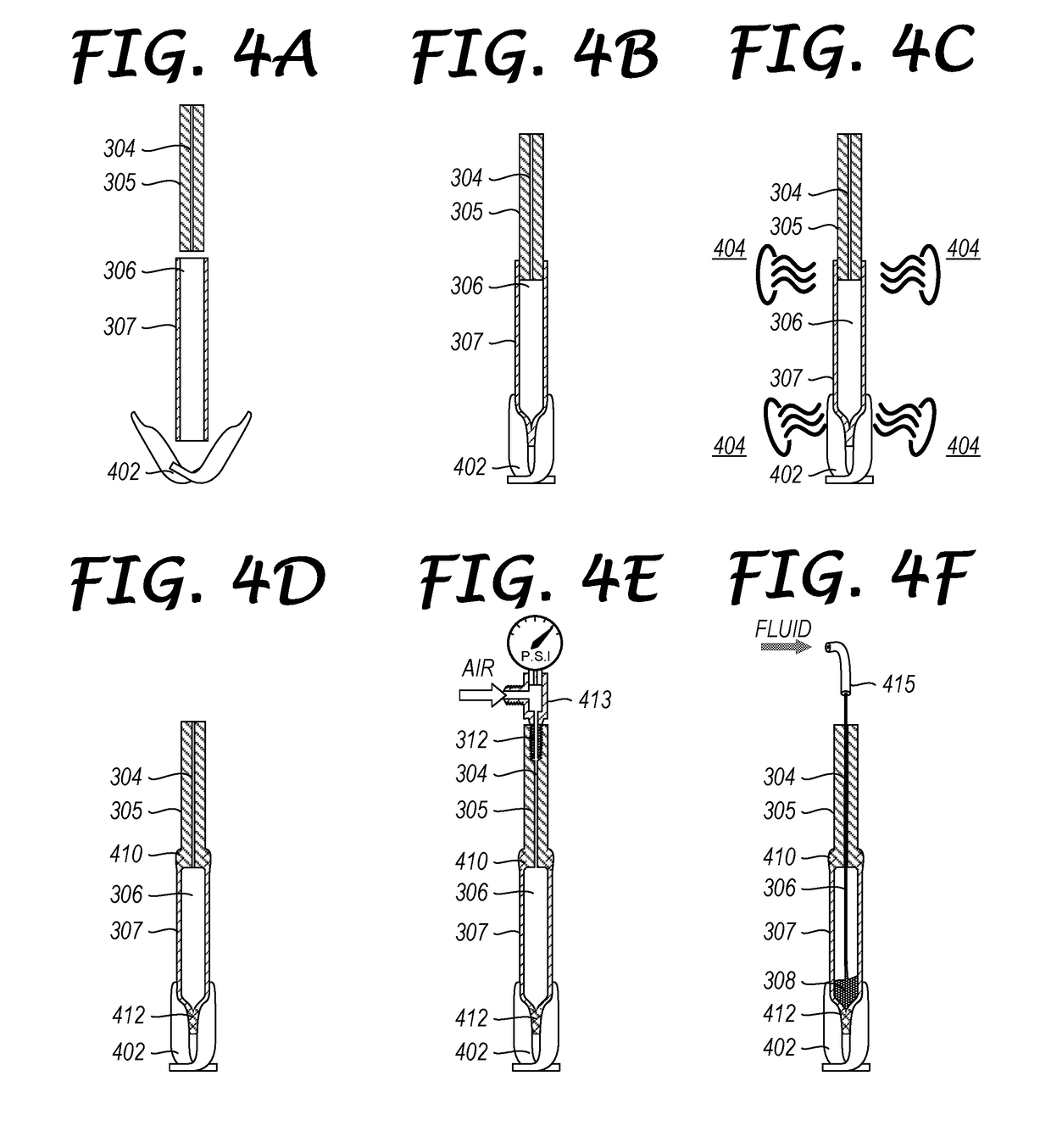
100: Deflection-Type Pressure Sensor102: Case103: (Pressurized) Fluid Medium104: Biased Diaphragm105: Measurement Chamber106: Magnet108: Hall Effect Linear Position Sensor110: Connection Pins112: Diaphragm Isolation Seal114: Protective Cap200: Piezo-Type Pressure Sensor202: Case204: Base206: Piezo-Electric Die207: Contacts208: Signal Amplifying Electronics210: Connection Pins300: Generic Low Pressure Sensor System302: OTS Low Pressure Sensor303: Temperature Thermistor304: Capillary Channel305: Support Mandrel306: Internal Pressure Chamber306-1′: Internal Pressure Chamber (Length l1′)306-2′: Internal Pressure Chamber (Length l2′)307: Pressure Bladder307-1: Pressure Bladder (Length l1)307-1′: Pressure Bladder (Length l1′)307-2′: Pressure Bladder (Length l2′)308: Measurement Fluid309: Hazardous Fluid Medium310: Compression Fitting / Tube Nut312: Male Threaded Port / Coupling315: Compression Fitting (Pressure Isolator)400: Low Pressure Sensor Syste...


PUM


Abstract

A pressure bladder comprising a substantially cylindrically shaped interior chamber is formed from a pliable, yet chemically resistant material, for example a fluoropolymer, such as FEP (fluorinated ethylene propylene). The interior chamber of the pressure bladder is hydraulically sealed at a distal end and is hydraulically coupled to a pressure sensor at a proximate end. Both the pressure bladder and pressure sensor are filled with an inert, non-reactive, stable measurement fluid. Optionally, a support mandrel with a second, smaller substantially cylindrically shaped interior chamber is hydraulically coupled between the pressure bladder and the pressure sensor and also filled with the measurement fluid. The pressure sensor is electrically coupled to electrical conductors, as is an optional thermistor. The conductors are received within a conductor protective tubing. The pressure sensor is disposed within a protective isolation tubing which is hydraulically coupled to the conductor protective tubing and to either the pressure bladder or support mandrel.

Description

BACKGROUND OF THE INVENTION[0001]The present invention is related to tanks, pipes, conduits and system used for containing and transporting gases, liquids and multiphase hazardous materials properties, especially those having corrosive and reactive properties.[0002]More particularly, the present invention is related to in situ measurement of the physical properties of the gasses, liquids and multiphase materials, especially those being designated as hazardous.[0003]Recently, the Environmental Protection Agency and the Department of Transportation, as well as many state and local jurisdictions, have promulgated new rules regarding the proper handling, storage and transportation of many classes of hazardous materials (Hazardous Materials Regulations (HMR) USC 49 Parts 100-185), as well as designated new material as being hazardous. These new rules include new and upgraded designs for railcar tanks, trailer-tanks and mariner containers, heightened standards for terrestrial storage and ...

Claims


Application Information

Patent Timeline
Patent Type & Authority Applications(United States)
IPC IPC(8): G01F23/284G01F23/70G05D9/12F03B15/06G01P5/14
CPCG01F23/284G01F23/706G01P5/14F03B15/06G05D9/12G01F23/14G01L9/14Y02E10/20
Inventor WESTMORELAND, III, AUBREY DARE
Owner WESTMORELAND III AUBREY DARE
Why Eureka
Try Eureka