Synthetic representation of a vascular structure

Active Publication Date: 2019-01-03
KONINKLJIJKE PHILIPS NV
View PDF7 Cites 4 Cited by
  • Summary
  • Abstract
  • Description
  • Claims
  • Application Information

AI Technical Summary

Benefits of technology

[0005]It would be advantageous to have an im

Problems solved by technology

However, the flattened schematic graph of the coronary arteries is far from the actual vascular structure as observed in an angiographic image, and as a re

Method used


Image

  • Synthetic representation of a vascular structure
  • Synthetic representation of a vascular structure
  • Synthetic representation of a vascular structure

Examples


Embodiment Construction

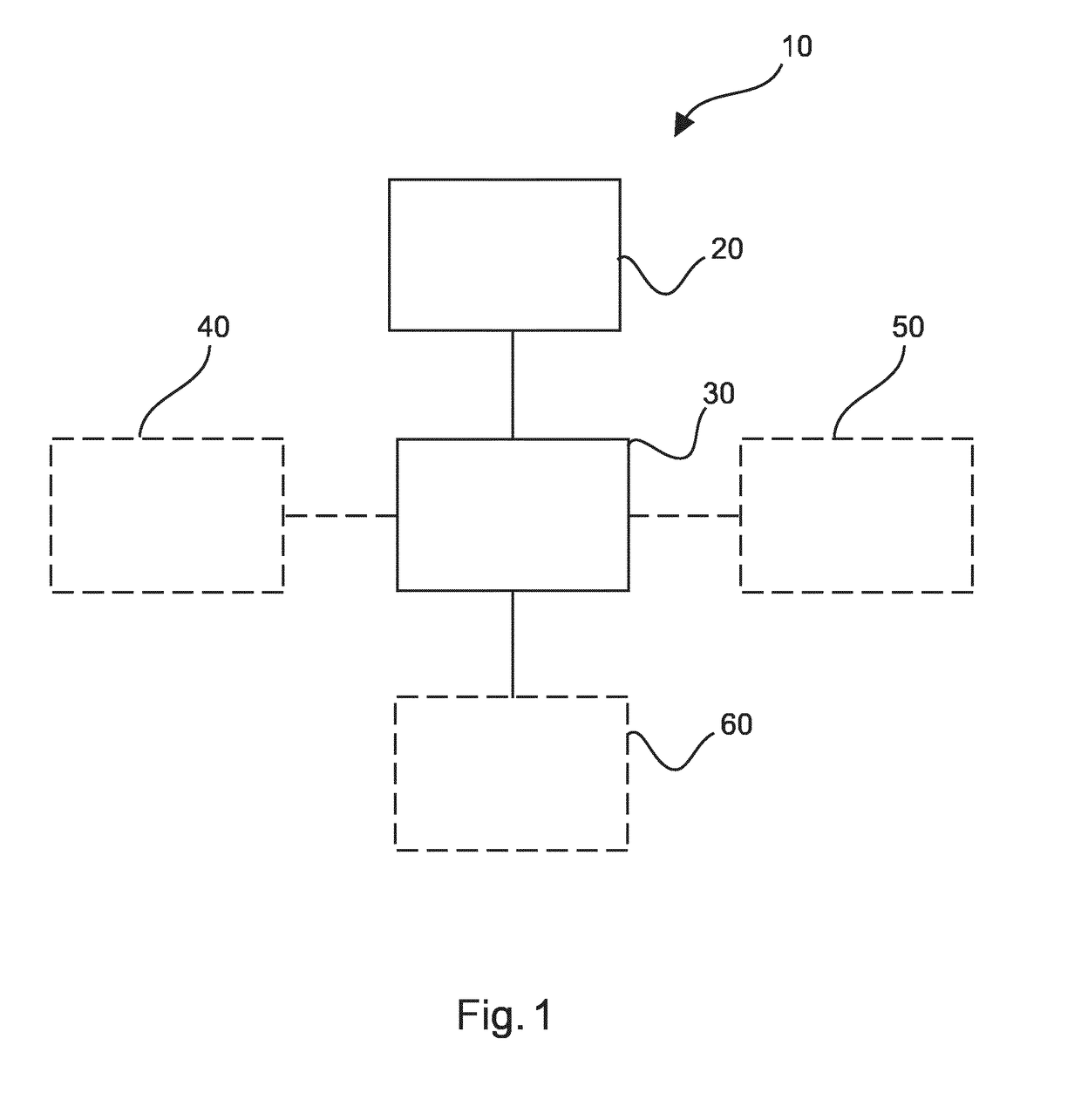
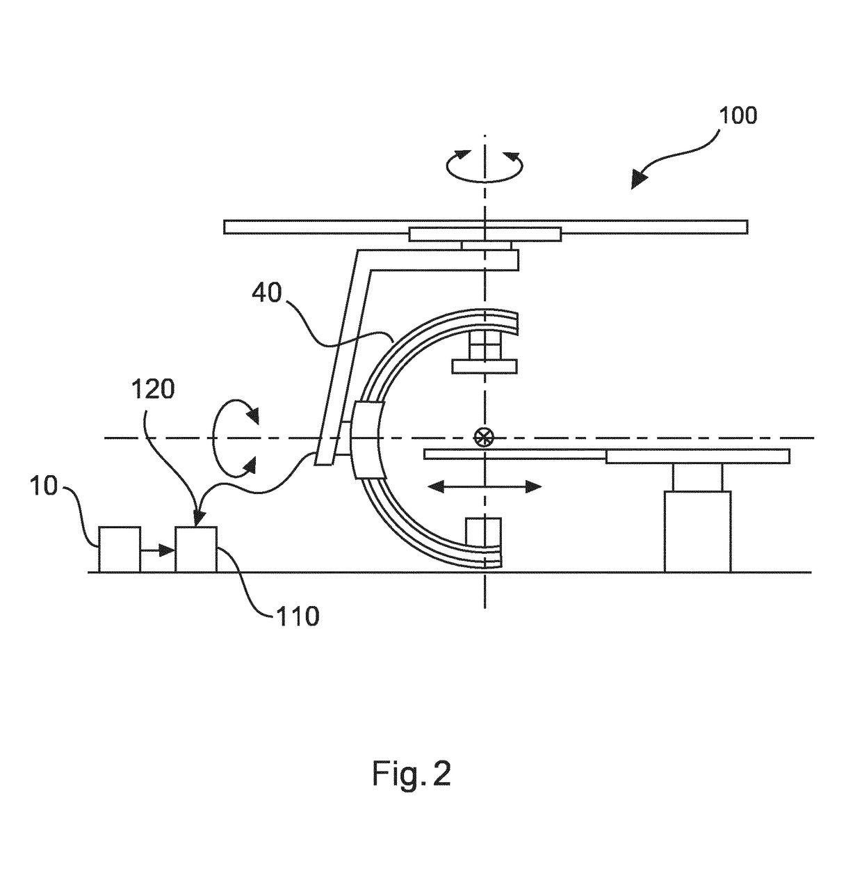
[0055]FIG. 1 shows an example of an apparatus 10 for providing a synthetic representation of a vascular structure. The apparatus comprises an input unit 20 and a processing unit 30. The input unit 20 is configured to provide at least one 2D X-ray image comprising 2D X-ray image data of a vascular structure of a patient's body part to the processing unit 30. The input unit 20 is also configured to provide a 3D model of the body part, the 3D model comprising a 3D modelled vascular structure to the processing unit 30. The processing unit 30 is configured to determine a 2D projection of the 3D model of the body part, the 2D projection of the 3D model of the body part comprising a 2D projection of the 3D modelled vascular structure. The processing unit 30 is also configured to transform the 3D model of the body part, wherein the transform of the 3D model of the body part comprises a determination of the pose of the 3D model of the body part such that a 2D projection of the 3D modelled va...


PUM


Abstract

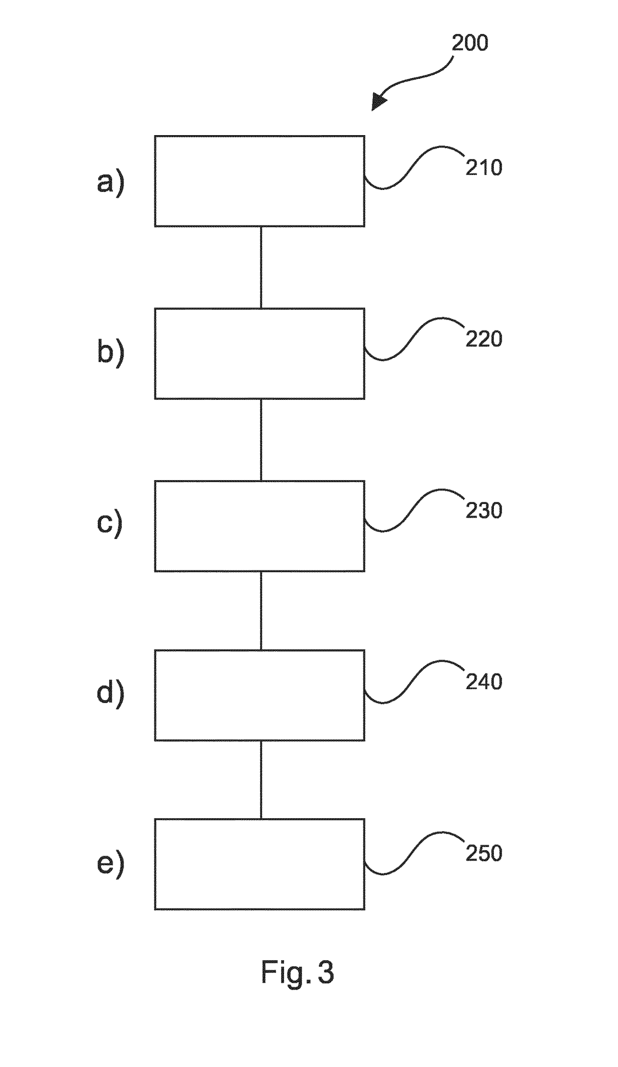
The present invention relates to an apparatus for providing a synthetic representation of a vascular structure. It is described to provide (210) at least one 2D X-ray image comprising 2D X-ray image data of a vascular structure of a patient's body part is provided. A 3D model of the body part is provided (220), the 3D model comprising a 3D modelled vascular structure. A 2D projection of the 3D model of the body part is determined (230), the 2D projection of the 3D model of the body part comprising a 2D projection of the 3D modelled vascular structure. The 3D model of the body part is transformed (240). The transform of the 3D model of the body part comprises a determination of the pose of the 3D model of the body part such that a 2D projection of the 3D modelled vascular structure associated with the transformed 3D model of the body part is representative of the 2D X-ray image data of the vascular structure of the patient's body part. A medical report is generated (250) based on information determined from the 3D model.

Description

FIELD OF THE INVENTION[0001]The present invention relates to an apparatus for providing a synthetic representation of a vascular structure to be typically integrated in an clinical interventional report, to a medical system for providing a synthetic representation of a vascular structure to be typically integrated in an clinical interventional report, and to a method for providing a synthetic representation of a vascular structure to be typically integrated in an clinical interventional report, as well as to a computer program element and a computer readable medium.BACKGROUND OF THE INVENTION[0002]In vascular treatments, for example in Percutaneous Transluminal Coronary Angioplasty (PTCA) to treat cardiac stenosis, information relating to the vascular treatments is required to be provided. Important findings of the vascular treatment are documented by annotating the flattened diagram of the coronary arteries. In particular, the clinician has to describe which stenosis was treated, f...

Claims


Application Information

Patent Timeline
IPC IPC(8): G06T19/20G06T11/00G16H30/20G16H15/00A61B6/00
CPCG06T19/20G06T11/008G16H30/20G16H15/00A61B6/504G06T2219/2016G06T2219/004G06T2210/41A61B2090/367G06T2219/2021G06T2207/10116G06T2207/10124G06T2207/30048G06T2207/30101G06T7/30
Inventor AUVRAY, VINCENT MAURICE ANDREGAURIAU, ROMANE ISABELLE MARIE-BERNARDFLORENT, RAOULGROTH, ALEXANDRAWEESE, JUERGEN
Owner KONINKLJIJKE PHILIPS NV
Why Eureka
Try Eureka