Resonator Device, Electronic Apparatus, And Vehicle

a technology of electronic equipment and resonance device, which is applied in the direction of oscillator, instrument, conversion using stochastic techniques, etc., can solve the problems affecting the performance of the device, and achieving the effect of reducing the size of the devi

Active Publication Date: 2019-01-03
SEIKO EPSON CORP
View PDF4 Cites 0 Cited by
  • Summary
  • Abstract
  • Description
  • Claims
  • Application Information

AI Technical Summary

Benefits of technology

[0005]An advantage of some aspects of the invention is to solve at least a part of the problems described above, and the invention can be implemented as the following forms or embodiments.

Problems solved by technology

Thus, it is difficult to realize reduction in size of the device.
In addition, since parasitic resistance and parasitic capacitance of a clock signal line that connects the crystal oscillators to an IC chip or circuit components increases, a problem such as degradation of performance occurs.

Method used


Image

  • Resonator Device, Electronic Apparatus, And Vehicle
  • Resonator Device, Electronic Apparatus, And Vehicle
  • Resonator Device, Electronic Apparatus, And Vehicle

Examples


modification example

7. Modification Example

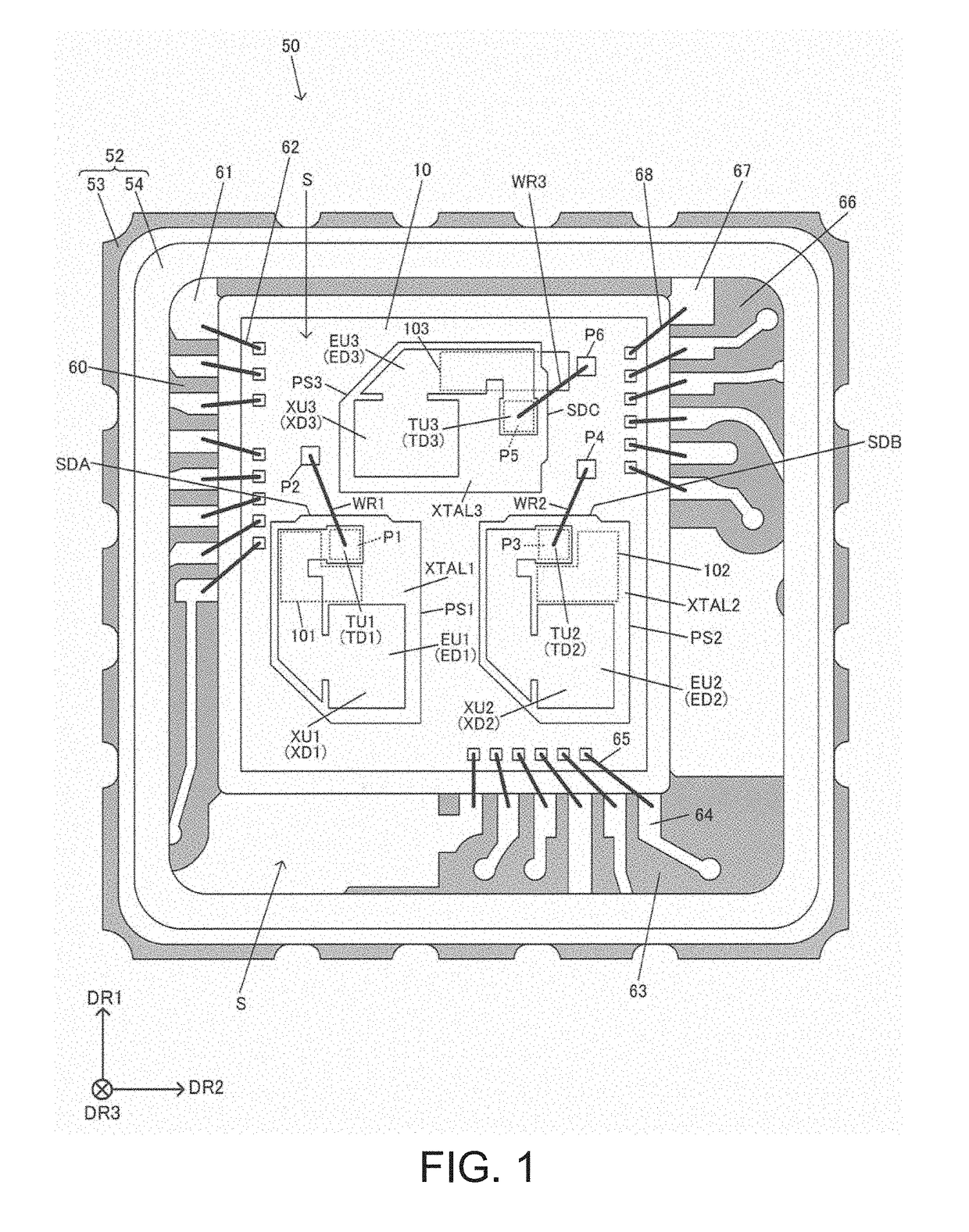
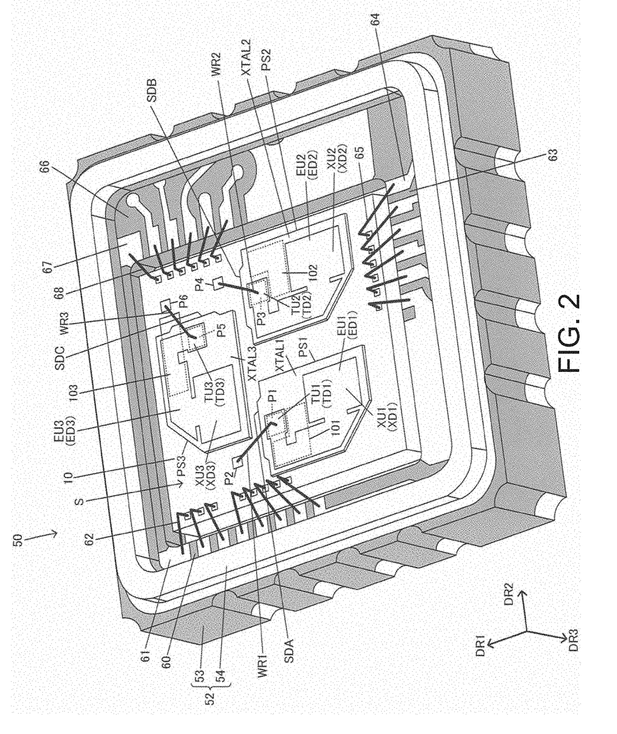
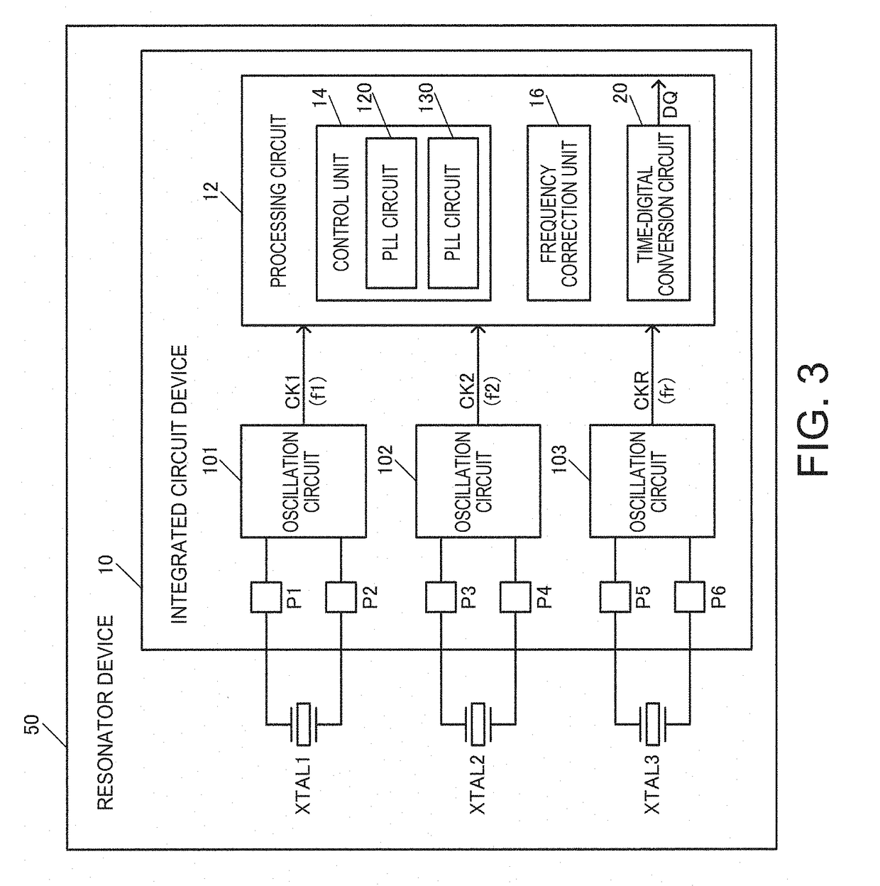
[0140]Next, various modification examples in the embodiment will be described. For example, in the embodiment, a case of providing the three resonators XTAL1 to XTAL3 is mainly described. However, the embodiment is not limited thereto. The number of resonators may be 2 or may be 4 or greater. For example, in the first modification example of the embodiment in FIG. 17, the two resonators XTAL1 and XTAL2 and one PLL circuit 120 are provided.

[0141]For example, the PLL circuit 120 performs phase synchronization between the clock signals CK1 and CK2. Specifically, in a case where the clock frequencies of the clock signals CK1 and CK2 are set to f1 and f2, the PLL circuit 120 performs phase synchronization between the clock signals CK1 and CK2 so as to satisfy N / f1=M / f2 (N and M are integers of 2 or greater, which are different from each other). The PLL circuit 120 includes the division circuits 122 and 124 and the phase detector 126. The division circuit 122 divide...


PUM


Abstract

A resonator device includes first and second resonators and an integrated circuit device. The integrated circuit device includes a first oscillation circuit configured to oscillate the first resonator, a second oscillation circuit configured to oscillate the second resonator, and a processing circuit configured to perform processing by using frequency difference information or frequency comparison information between a first clock signal generated by oscillating the first resonator and a second clock signal generated by oscillating the second resonator. The first resonator is supported on the integrated circuit device by a first support portion. The second resonator is supported on the integrated circuit device by a second support portion.

Description

BACKGROUND1. Technical Field[0001]The present invention relates to a resonator device, an electronic apparatus, and a vehicle.2. Related Art[0002]In a resonator device that oscillates a resonator such as a piezoelectric resonator so as to generate a clock signal, size reduction is required. For example, JP-A-2003-309296 discloses an integrated circuit device in which an integrated circuit including a piezoelectric resonator, a clock signal generation circuit, and a CPU is mounted on a chip board, and thus one chip is achieved by integrally integrating the integrated circuit including the piezoelectric resonator. At this time, the clock signal generation circuit is connected to the piezoelectric resonator and generates a clock signal and the CPU operates based on the generated clock signal.[0003]JP-A-5-87954 discloses a technology of realizing time-digital conversion by using two crystal oscillators, in the related art. In the technology of the related art disclosed in JP-A-5-87954, ...

Claims


Application Information

Patent Timeline
Patent Type & Authority Applications(United States)
IPC IPC(8): H03B5/32H03H9/05G04F10/00H03M1/04
CPCH03B5/32H03H9/0542G04F10/005H03M1/04H03B5/323H03B5/362H03B5/368H03H9/0547
Inventor TSUTSUMI, AKIOKURASHINA, TAKASHIKOMATSU, FUMIKAZU
Owner SEIKO EPSON CORP
Why Eureka
Try Eureka