
Method for forming a collar in a muffler housing

Active Publication Date: 2019-01-24
BOSAL EMISSION CONTROL SYST
View PDF0 Cites 0 Cited by
  • Summary
  • Abstract
  • Description
  • Claims
  • Application Information

AI Technical Summary

Benefits of technology

The patent describes a method for making an outwardly projecting collar around the exhaust gas opening by flaring the edge of the metal sheet surrounding the exhaust gas opening and increasing the size of the exhaust gas opening by moving a collar forming head along the rotational axis. The collar is formed in a gradual process using the collar forming head, which allows for a gentle formation of the collar in the muffler housing. The technical effects of the patent text are improved gas flow and reduced noise in the muffler.

Problems solved by technology

Problems occur, however, during formation of the collar at such highly curved positions, such as rupture of the muffler shell sheet and reproducibility of the tubular connection regarding, for example, tube welding.
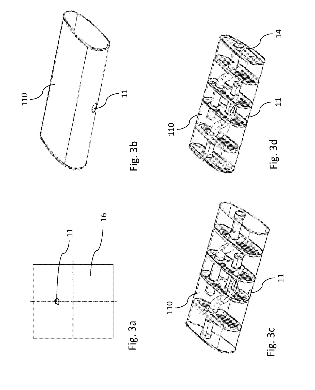
Therefore, making the collar hole on the side of the transverse muffler is a technical challenge, especially for very flat mufflers where the collar has to be made in an area of the muffler shell where the radius of the muffler shell is very small and hence strongly curved.
The existing methods have drawbacks for making collars in highly curved sheets such as in flat transverse mufflers with a collar situated in the curved region of the muffler shell.
One drawback is that the material the muffler shell is made of, generally steel, cannot flow sufficiently from the highly curved muffler shell to the corner when pulling the die through the hole.
When a crack occurs in the collar, the muffler shell or even the entire muffler has to be scrapped because the connection between the muffler and the exhaust tube would not be durable and leak-tight.
Such deformation of the muffler housing is not acceptable and the muffler housing has to be scrapped.
Therefore, this procedure is a very time-consuming and very expensive multiple step process which does not ensure proper collar formation without cracks.
Crenations have a negative impact on the durability of weld connections between the exhaust pipe and the side entry collar, making additional steps of machining necessary to eliminate crenations.
Besides such additional machining step being time-consuming and expensive, the metal burrs or particles generated by machining are not desired, as they may get trapped in the end product.
Such metal burrs or particles may then cause rattling noises in the muffler.
Removal of machining burrs, constantly cleaning the tools etc., once again increase the complexity and the costs of the production.

Method used


Image

  • Method for forming a collar in a muffler housing
  • Method for forming a collar in a muffler housing
  • Method for forming a collar in a muffler housing

Examples


Embodiment Construction

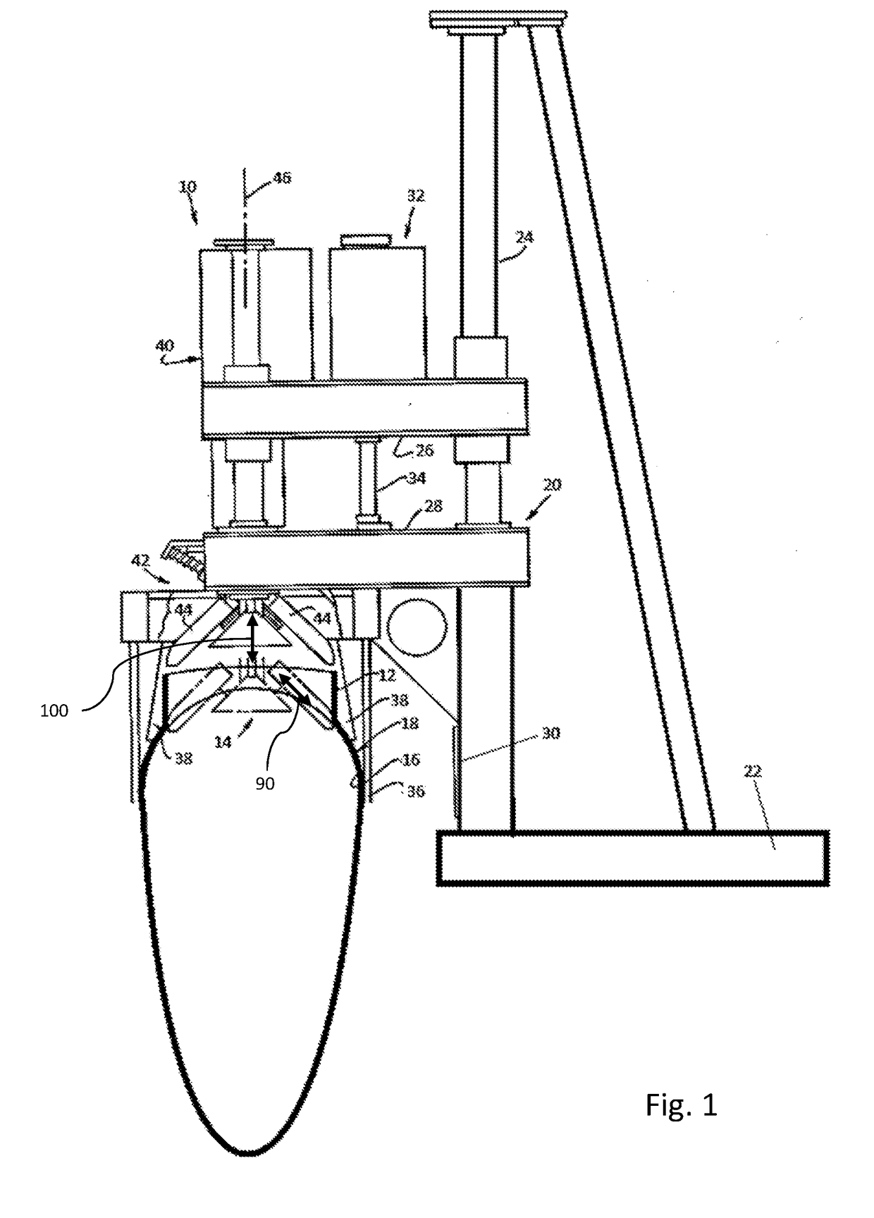
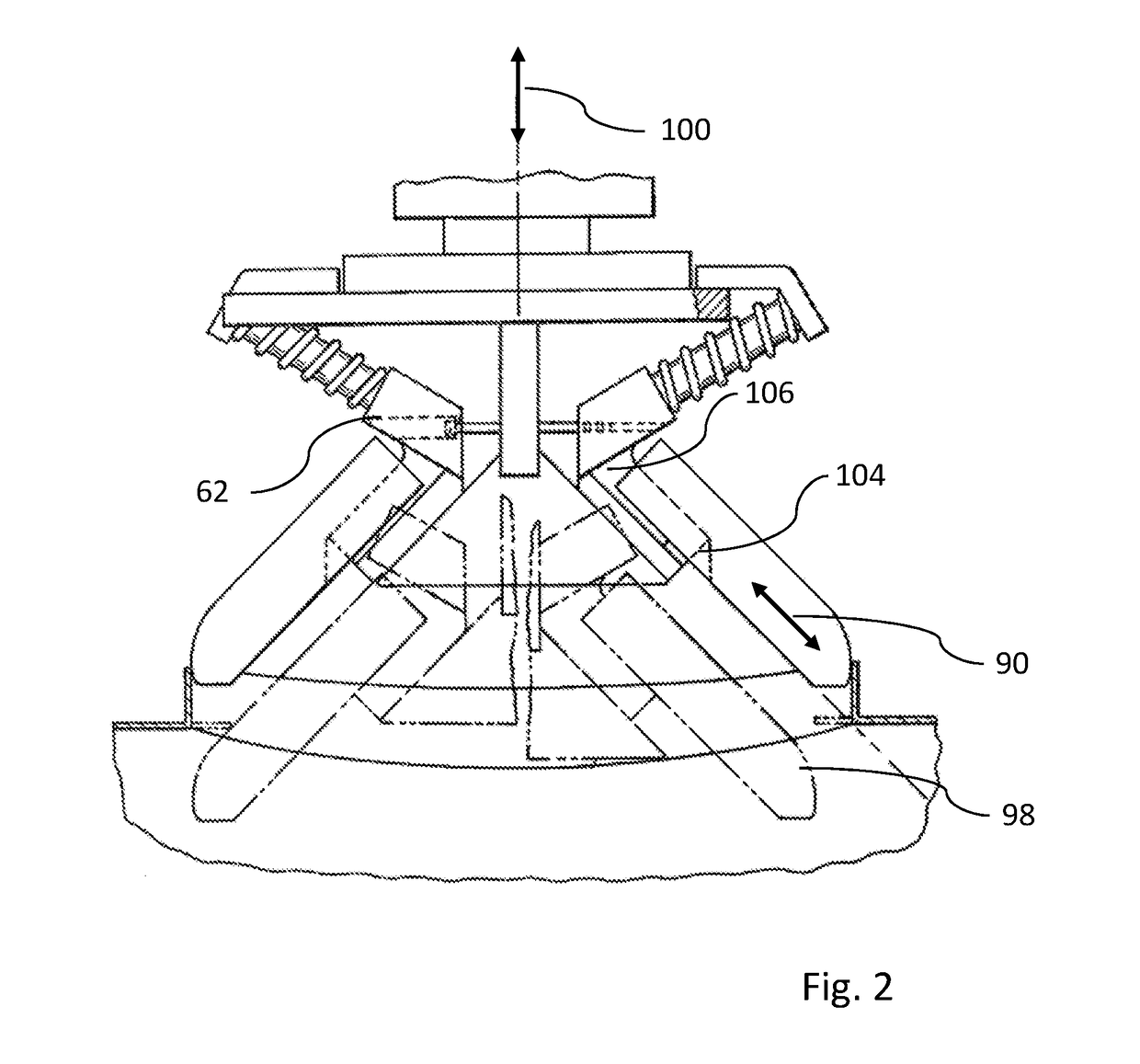
[0062]Referring to the drawing, the collar forming apparatus of the present invention, indicated generally at 10, is shown in FIG. 1 in a position immediately subsequent to the formation of a collar or neck 12 around an exhaust gas opening 14 in the metal sheet 16 of a muffler shell 18. The collar forming apparatus 10 includes a frame 20 having a base 22 to which upright support columns 24 (one shown) are secured. A pair of vertically spaced apart tables 26 and 28 is slidably mounted to the support columns 24 for movement relative to the base 22 and for movement relative to each other. A hydraulic cylinder 30 is interposed between the base 22 and the lower table 28 and is operable to raise and lower the table 28. A vertical displacement actuator 32 having a rod 34 connects the upper table 26 with the lower table 28 in an adjusted fixed position so that operation of the hydraulic cylinder 30 causes simultaneous movement of the tables 26 and 28, while operation of the vertical displac...


PUM

PropertyMeasurementUnit
Sizeaaaaaaaaaa

Abstract

Method for forming a collar in a muffler shell including:providing a muffler shell made of a metal sheet and forming a muffler housing, the muffler shell having an exhaust gas opening,providing a collar forming head having a rotational axis and at least two movable expanders,introducing a collar forming head into a muffler housing,moving the expanders of the collar forming head introduced into the muffler shell radially away from the rotational axis of the collar forming head from a retracted position to an expanded positionrotating the collar forming head around the of the collar forming head,bringing the rotating expanded collar forming head in contact with the metal sheetforming an outwardly projecting collar around the exhaust gas opening by flaring the edge of the metal sheet.

Description

FIELD OF THE INVENTION[0001]The present invention relates to a method for forming a collar in a muffler housing of a muffler for an internal combustion engine.BACKGROUND[0002]Due to increasing flexibility requirements as well as the requirements to have common components for different vehicle platforms, mufflers, in particular rear mufflers, tend to be designed to accommodate the space below the trunk in a direction transverse to the driving direction. Such transverse muffler also allows for very easy design and integration of two tail pipes which are arranged on each side of the back of the vehicle. The transverse muffler is then located at the rear of the car beneath the trunk in a direction parallel to the rear axle. Although this arrangement allows the use of the distance between the two wheels, hence allowing a muffler length of up to 800 mm and more, this arrangement, however, requires that the height of the transverse muffler has to be reduced, in order to maintain the trunk ...

Claims


Application Information

Patent Timeline
IPC IPC(8): F01N1/08B21D53/88B21B17/02
CPCF01N1/083B21D53/88B21B17/02B21D39/00B21D41/02B21D19/02B21D22/14B21D22/18F01N13/08F01N13/18F01N13/1805F01N13/1861F01N13/1872F01N13/1888F01N1/00F01N1/02F01N1/08F01N2450/20F01N2450/22F01N2470/02F01N2470/14F01N2470/16F01N2470/18F01N2470/26F01N2490/02F01N2490/08F01N2490/15B21D19/088
Inventor VANLEENE, PAUL
Owner BOSAL EMISSION CONTROL SYST
Learn More