Architecture for a system of integrated pumps, mixers, and gates for microfluidic devices

a microfluidic device and integrated pump technology, applied in the direction of machines/engines, positive displacement liquid engines, transportation and packaging, etc., can solve the problems of zeta, permittivity, and bubble formation problems, and the bias towards non-mechanical electroosmotic pumps are limited to conducting liquids

Inactive Publication Date: 2019-01-24
JALALI MIR ABBAS
View PDF0 Cites 0 Cited by
  • Summary
  • Abstract
  • Description
  • Claims
  • Application Information

AI Technical Summary

Benefits of technology

[0010]In one aspect, a microfluidic chip with the capability of overcoming undesired sedimentation and separation of fluids...

Problems solved by technology

This demand has caused a bias towards adopting non-mechanical pumps, mostly those based on electrowetting and electroosmosis.
Moreover, electroosmotic pumps are limited to conducting liquids and suffer from permittivi...

Method used


Image

  • Architecture for a system of integrated pumps, mixers, and gates for microfluidic devices
  • Architecture for a system of integrated pumps, mixers, and gates for microfluidic devices
  • Architecture for a system of integrated pumps, mixers, and gates for microfluidic devices

Examples


Embodiment Construction

[0039]While various aspects and features of certain embodiments have been summarized above, the following detailed description illustrates at least on exemplary embodiment in further detail to enable one skilled in the art to practice such an embodiment. The described example is provided for illustrative purposes and is not intended to limit the scope of the invention.

[0040]In the following description, for the purposes of explanation, numerous specific details are set forth in order to provide a thorough understanding of the described embodiment / s. It will be apparent to one skilled in the art, however, that other embodiments of the present invention may be practiced without some of these specific details. While various features are ascribed to different embodiments, it should be appreciated that the features described with respect to one embodiment may be incorporated with other embodiments as well. By the same token, however, no single feature or features of any described embodim...


PUM


Abstract

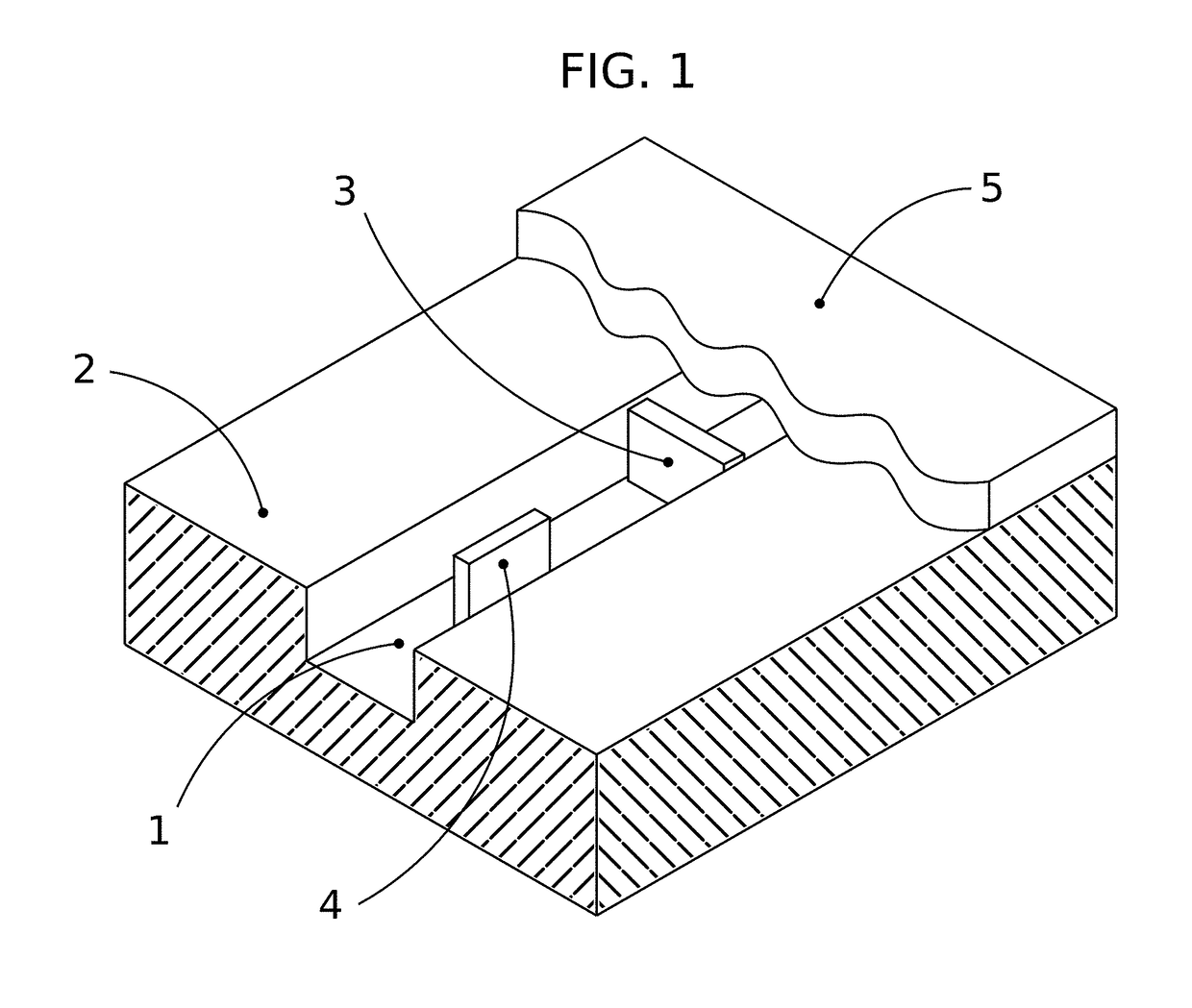
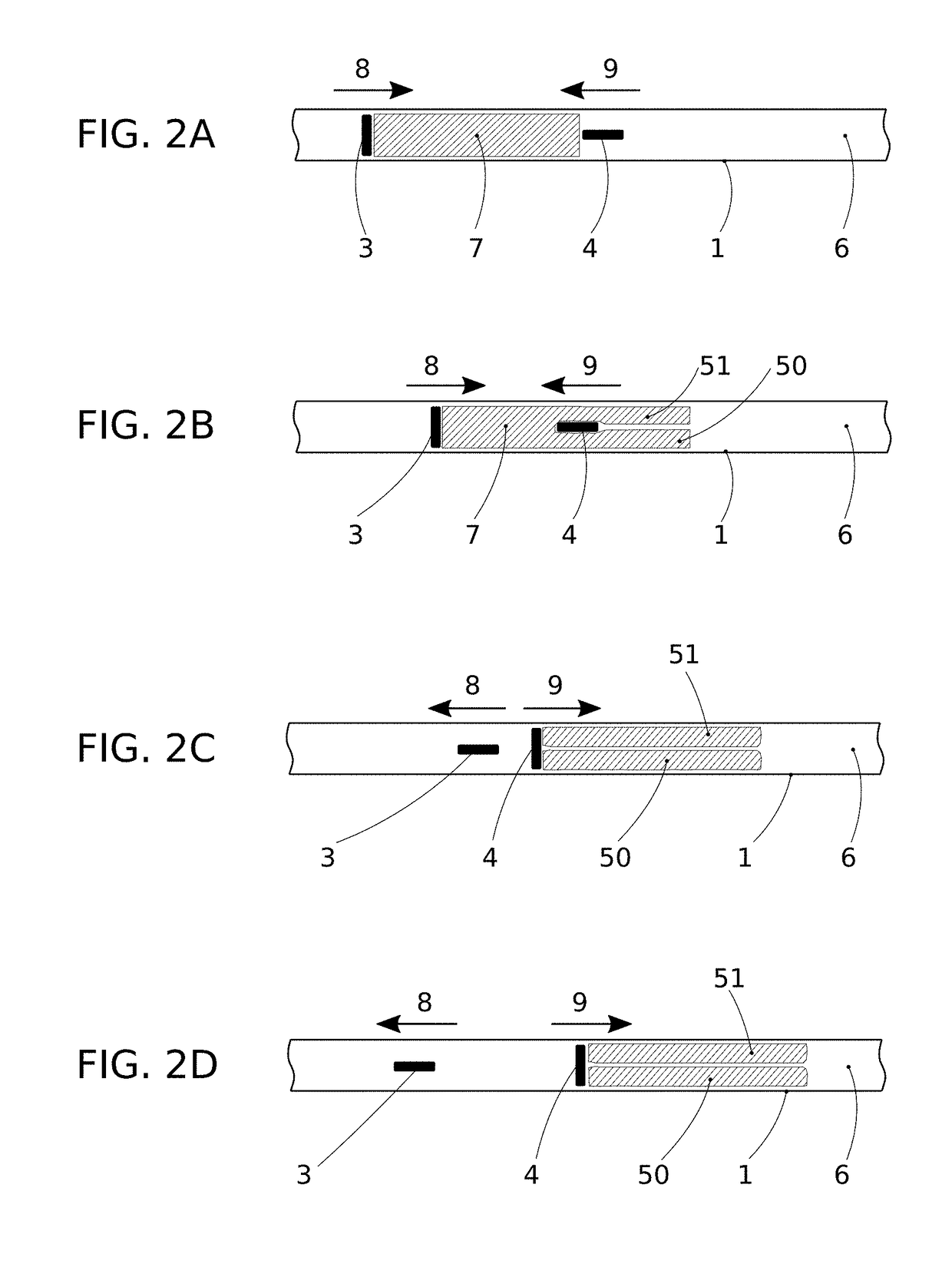
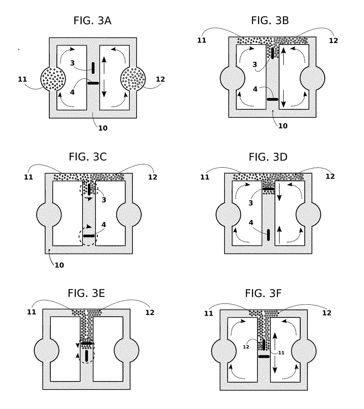
A single, or a cascade of magnetically actuated blades are used to simultaneously pump and mix fluids in continuous-flow microfluidic devices. The external magnetic field, which traps the blade and controls its motion, is generated by a carpet of micron-scale coils. The frequencies and amplitudes of the blade's translational and rotational motions are controlled by voltage and current waves that pass through the carpet of the microcoils. When the frequency ratios of the translational and rotational motions of the blades do not commensurate, the pumped fluid is mixed chaotically. Chaotic mixing is also achieved when a single blade moves on a rosette-like quasi-periodic path. The invented micro pumping and mixing device negates connections to external pumps, and does not need specially-carved channels to mix flowing liquid. The microcoils are printed or installed on glass or polymeric substrates. The blades can also be used as controllable gates in microfluidic circuits. The blades are embedded and sealed in microchannels or pumping chambers; the device composed of the blades and microcoils is disposable.

Description

COPYRIGHT STATEMENT[0001]A portion of the disclosure of this patent document contains material that is subject to copyright protection. The copyright owner has no objection to the facsimile reproduction by anyone of the patent document or the patent disclosure as it appears in the Patent and Trademark Office patent file or records, but otherwise reserves all copyright rights whatsoever.FIELD[0002]The present disclosure relates, in general, to microfluidic devices, and more particularly to technology of electromagnetic mechanical devices for the pumping, mixing and segregation of fluids in a microfluidic devices.BACKGROUND[0003]Microfluidic devices currently represent the hot technology for systems in which low volumes of fluids are processed to achieve multiplexing, automation, and high-throughput screening. In these devices, precise control and manipulation is necessary for fluids that are geometrically constrained to a small, typically sub-millimeter scale passage, generally on a ...

Claims


Application Information

Patent Timeline
IPC IPC(8): F04B19/00F04B17/03B01F13/00B01F11/00
CPCF04B19/006B01F11/0071B01F13/0059F04B17/03B01F33/30B01F33/452B01F31/65
Inventor JALALI, MIR ABBAS
Owner JALALI MIR ABBAS
Why Eureka
Try Eureka