Bidirectional dc/dc converter and method for charging the intermediate circuit capacitor of a dc/dc converter from the low-voltage battery

a dc/dc converter and intermediate circuit technology, applied in battery/fuel cell control arrangement, process and machine control, instruments, etc., can solve the problems of high current flow and rapid increase of current, and achieve the effect of smoothing voltage spikes

Active Publication Date: 2019-01-24
ROBERT BOSCH GMBH
View PDF0 Cites 10 Cited by
  • Summary
  • Abstract
  • Description
  • Claims
  • Application Information

AI Technical Summary

Benefits of technology

[0013]One advantage of the present invention that it may be used universally in all these converter types.
[0014]The second winding of the discharge transformer and the discharge diode are biased in such a way that, if the discharge switch is activated, a current in the series inductor which induces a voltage which is opposite the low voltage may be discharged via the second winding into the low-voltage battery, wherein the current is rectified via the discharge diode.
[0015]One or a plurality of damping capacitors which are connected in parallel with the low-voltage battery, and a series circuit which comprises a damping resistor and a damping capacitor and which is connected in parallel to the series circuit comprising a series inductor and a low-voltage battery, are used for the advantageous smoothing of voltage spikes during the switching operations in the low-voltage region.
[0016]A second aspect of the present invention relates to the method for charging the intermediate-circuit capacitor with energy from the low-voltage battery. This takes place via a sequence of controlled current pulses in two phases:
[0017]In the first phase, there are initially short current pulses respectively having a correspondingly long subsequent dead time, during which the low-voltage battery is disconnected from the transformer. The current pulses become continuously longer and the idle times become shorter, and the intermediate-circuit capacitor thus charges until the dead time of zero has been reached. In this phase, the series inductor is discharged during the respective dead time via its second winding.
[0018]In the second phase, the current pulses flowing through the low-voltage transformer winding are gradually shortened again, wherein the diodes in the low-voltage network are switched to the conductive state during the intermediate intervals. As a result, the transformer winding in the low-voltage network is short-circuited. These short-circuit intervals become longer. However, the discharge switch is now open, so that the series inductor, which is directly adjacent to the low-voltage battery during the short-circuit period, can recharge, and can thus provide for an ever-higher induction voltage at the intermediate-circuit capacitor during the next pulse, until the desired setpoint value has been reached.

Problems solved by technology

If the high-voltage battery were to be spontaneously reconnected to the high-voltage network, potentially high and rapidly increasing currents would flow in particular due to the recharging of the intermediate-circuit capacitor.

Method used


Image

  • Bidirectional dc/dc converter and method for charging the intermediate circuit capacitor of a dc/dc converter from the low-voltage battery
  • Bidirectional dc/dc converter and method for charging the intermediate circuit capacitor of a dc/dc converter from the low-voltage battery
  • Bidirectional dc/dc converter and method for charging the intermediate circuit capacitor of a dc/dc converter from the low-voltage battery

Examples


Embodiment Construction

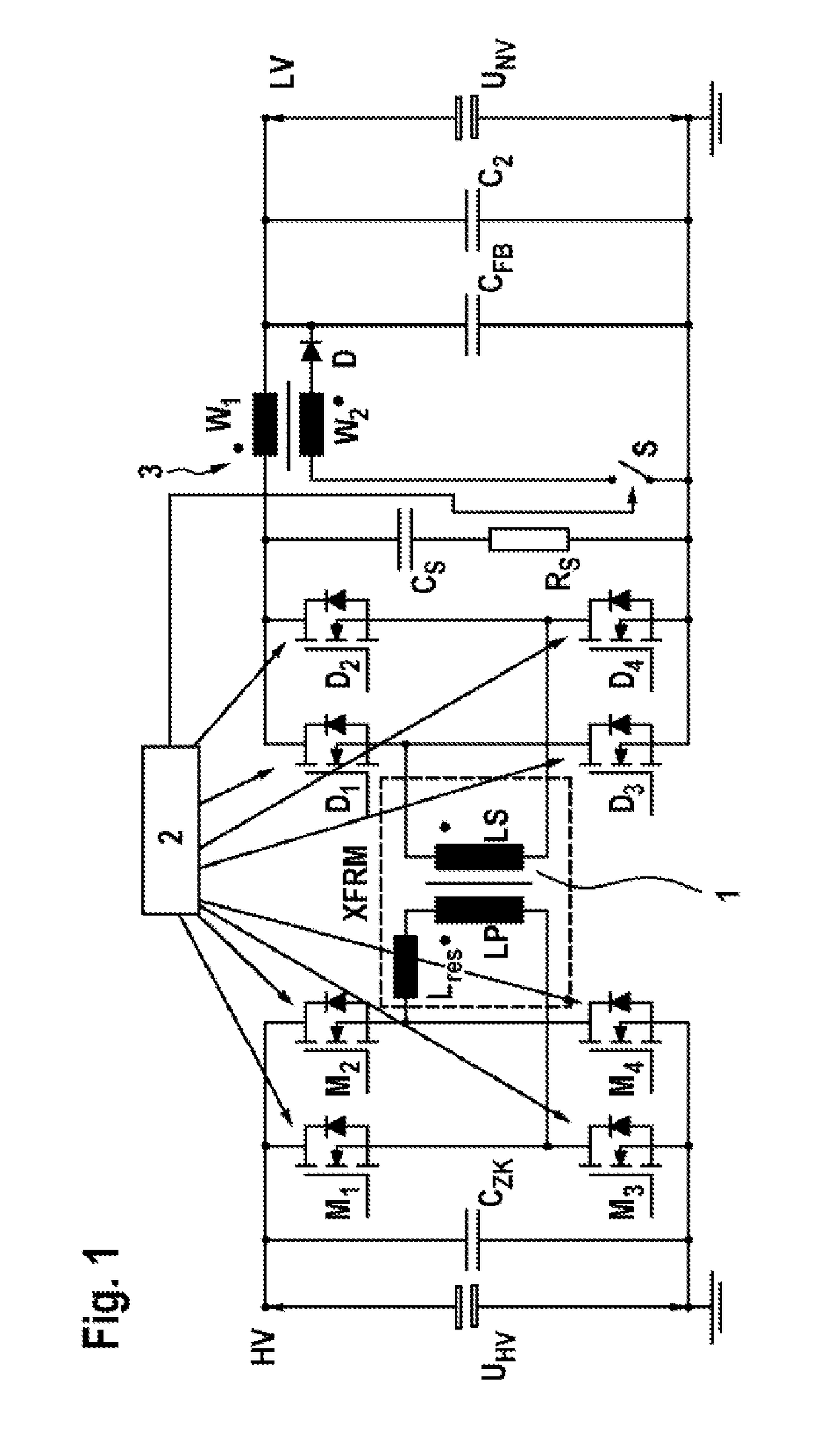
[0032]FIG. 1 shows the circuit of a single-phase full-bridge phase-shifted (FBPS) DC / DC converter, which is one possible type of converter in which it is possible to charge the intermediate-circuit capacitor CZK from the low-voltage battery UNV, starting from the voltage of zero volts, via modifications which will be described in detail below. However, the modifications may be used on any forward converter having galvanic isolation and a current-fed high-voltage intermediate circuit, for example, with push-pull converters or multilevel converters.

[0033]The FBPS converter depicted in FIG. 1 comprises a transformer 1 which, in normal operation, is fed by the high-voltage battery UHV which is connected to the terminal HV. Switches M1 to M4 switch this voltage at a clock frequency of several kHz, with alternating signs, to the primary winding of the transformer 1, whereby its core, alternating periodically, is magnetically charged. Thus, by means of a control device 2, the switches M1 a...


PUM


Abstract

The invention relates to a bidirectional DC/DC converter for transmitting energy between a high-voltage grid (HV) and a low-voltage grid (LV), comprising connections for a high-voltage battery (UHV) and a low-voltage battery (UNV). The converter comprises the following:—one or more transformers (1) for galvanically isolating the low-voltage grid (LV) from the high-voltage grid (HV), an intermediate circuit capacitor (CZK) in the high-voltage grid (HV),—electronic switches (D1 to D4, M1 to M4) for connecting and reversing the polarity of the coil of the transformer (1) on the high-voltage grid (HV) and on the low-voltage grid (LV),—a controller (2) for controlling the electronic switches (D1 to D4),—and a series inductance (W1) in the low-voltage grid (NV). The series inductance (W1) is designed as a discharge transformer (3) for discharging the energy stored in the series inductance (W1), wherein a second coil (W2) is connected in series to a discharge switch (S) and a diode (D), and the series inductance (W 1) is discharged to the low-voltage battery (UNV) when the discharge switch (S) is activated. The invention additionally relates to a method for charging the intermediate circuit capacitor (CZK) of the converter to the high-voltage grid potential from the low-voltage battery (UNV).

Description

BACKGROUND OF THE INVENTION[0001]The present invention relates to a bidirectional DC / DC converter which comprises an augmentation which enables charging the intermediate-circuit capacitor to the voltage of the high-voltage network using electrical energy from the low-voltage battery, and the present invention also comprises a method for charging the intermediate-circuit capacitor via this converter.[0002]DC / DC converters are supplied by a DC voltage source and provide the consumer with the electrical energy in the form of DC voltage at a different voltage level. The terms high-voltage network and low-voltage network are used here.[0003]For example, the drive motor of electric or hybrid vehicles is driven by the high-voltage network at a voltage of several hundred volts, while the low-voltage vehicle electrical system generally has a voltage of 12 volts or occasionally 24 or 48 volts. Both networks have a respective battery and are interconnected via a DC / DC converter, which contribu...

Claims


Application Information

Patent Timeline
Patent Type & Authority Applications(United States)
IPC IPC(8): H02J7/00B60L11/18H02M1/36H02M3/335H02M3/337
CPCH02J7/0065B60L11/1868H02J7/0054H02M1/36H02M3/33584H02M3/3376B60L2210/10H02J2007/0059H02M2001/322B60L58/20H02J7/342H02J2207/20H02M1/322Y02T10/70Y02T10/72B60L3/0046
Inventor CARRIZALES, EMILIANO GUDINO
Owner ROBERT BOSCH GMBH
Why Eureka
Try Eureka