Camera module

a technology of camera module and camera body, applied in the field of camera module, can solve problems such as damage during fitting, and achieve the effects of reducing the degree of hardness, improving the sealing ability of clearance, and adequate flexibility of compensating elements

Active Publication Date: 2019-01-24
ROSENBERGER HOCHFREQUENZTECHNIK GMBH & CO KG
View PDF1 Cites 7 Cited by
  • Summary
  • Abstract
  • Description
  • Claims
  • Application Information

AI Technical Summary

Benefits of technology

[0018]The compensating element according to the invention advantageously has a lower degree of hardness than an O-ring of a comparable diameter. Suitable degrees of hardness for the compensating element according to the invention are in particular between 30 Shore and 50 Shore. A degree of hardness in the specified range ensures adequate flexibility of the compensating element, to compensate for the clearance between the covering element and the camera module housing.
[0019]A particularly suitable compensating element is formed as a three-dimensional lip seal. Lip seals have improved clearance sealing capabilities in particular in comparison with two-dimensional O-rings. Moreover, small amounts of water are helpful during sealing, in that water penetrates into the gap between the lips and presses the lip seal against the housing wall. Furthermore, lip seals have a longer service life, for example in comparison with O-rings.
[0020]Particularly advantageous is a substantially H- or dumbbell-shaped cross section of the compensating element. Accordingly, the compensating element has two parallel limbs and a central cross-piece between the limbs. This cross-sectional

Problems solved by technology

Among the factors that are decisive for this is the minimization of axially acting forces, since axial forces can cause leakages in the camera mod

Method used


Image

  • Camera module
  • Camera module
  • Camera module

Examples


Embodiment Construction

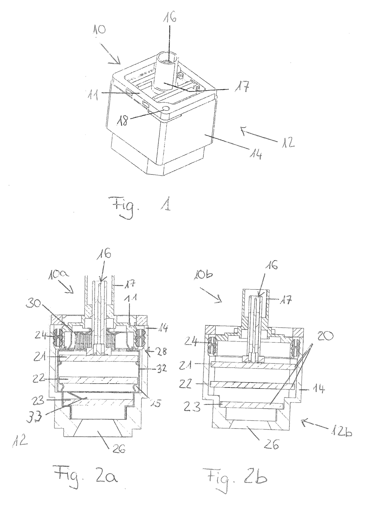
[0039]FIG. 1 shows a schematic perspective view of an embodiment of a camera module 10 according to the invention. The camera module 10 has a covering element 11 and a camera module housing 12 with a peripheral wall 14. The covering element 11 includes an interface 16, which is arranged in an interface enclosure 17. The interface may be formed for example as a Fakra, HSD, MTD or similar interface.

[0040]In FIG. 1, the covering element 11 is screwed to the camera module housing 12 at two fastening points or holes 18.

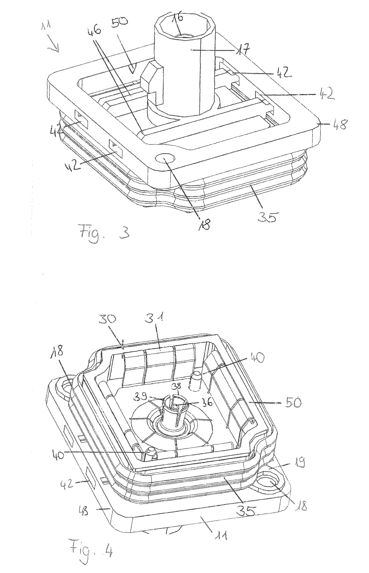
[0041]FIG. 2a shows a schematic sectional view of an embodiment of a camera module 10a according to the invention. In a way corresponding to the camera module 10 from FIG. 1, the camera module 10a in FIG. 2a comprises a covering element 11, a camera module housing 12 made of plastic and also an interface 16. Moreover, in FIG. 2a, the printed circuit board assembly 20 is shown with the printed circuit boards 21, 22 and 23, the compensating element 24, the lens 26, the EMC m...


PUM


Abstract

The present invention relates to a camera module, for use in the automobile sector, with a printed circuit board assembly, the printed circuit board assembly comprising at least one printed circuit board and an image sensor; an interface for data transmission, which makes contact with the printed circuit board; a camera module housing, which has a peripheral wall; an interface-side covering element; a compensating element, which is arranged between the peripheral wall and the covering element; the compensating element being designed to seal the camera module housing and compensate for a clearance between the covering element and the peripheral wall. The present invention also relates to a motor vehicle with a camera module according to the invention and also to a method for producing it.

Description

FIELD OF THE INVENTION[0001]The present invention relates to a camera module for use in the automobile sector.TECHNICAL BACKGROUND[0002]Cameras in the automobile sector have long been a commonly used means for increasing safety and convenience for a motor vehicle driver. Such cameras must withstand considerable daily stresses as a result of dirt, water and mechanical loads.[0003]To provide the required robustness of such a camera module, camera module housings are often produced from metal, in particular from aluminum.[0004]However, housings made of metal, in particular of aluminum, have been found to be disadvantageous because of higher material costs and also considerable effects of wear in the case of metal-processing tools.[0005]Against this background, WO 2013 / 085796 A1 discloses a radial seal for a camera housing made of plastic.[0006]A disadvantage of this, however, is that a housing cover must be laboriously screwed to the housing at four fastening points. What is more, the ...

Claims


Application Information

Patent Timeline
IPC IPC(8): H04N5/225H05K1/02
CPCH04N5/2252H04N5/2253H05K1/0213H01R13/5202H01R24/50H04N23/57H01R2201/26H04N23/51H04N23/54
Inventor BIPPUS, RAINERSCHMID, JOHANNES
Owner ROSENBERGER HOCHFREQUENZTECHNIK GMBH & CO KG
Why Eureka
Try Eureka