
Driving system for actuating and sensing module

a technology of sensing module and driving system, which is applied in the direction of positive displacement liquid engine, instruments, machines/engines, etc., can solve the problems of saving a lot of space, actuating and sensing devices may not be equipped with a power source itself, etc., and achieves a large reduction of the response time of the sensor to the fluid, increase the flow rate of fluid, and provide the effect of fluid stably and uniformly

Active Publication Date: 2019-01-31
MICROJET TECH
View PDF0 Cites 8 Cited by
  • Summary
  • Abstract
  • Description
  • Claims
  • Application Information

AI Technical Summary

Benefits of technology

The present invention provides a driving system for an actuating and sensing module. This system includes an actuating and sensing device and a power supply device. The actuating device is used to increase the flow rate of fluid and provide the amount of fluid stably and uniformly. The sensor measures the fluid with precision, and the actuating device and sensor are integrated as a modularized structure. This allows for easy installation and reduces space requirements. The system can be used for monitoring air quality in electronic devices. The technical effects of this invention are improved precision in fluid monitoring and a simplified installation process.

Problems solved by technology

The actuating and sensing device may not be equipped with a power source itself.
Accordingly, the configuration described above saves a lot of space when installing the entire module, and the purpose of minimizing the design of the module is achieved.

Method used


Image

  • Driving system for actuating and sensing module
  • Driving system for actuating and sensing module
  • Driving system for actuating and sensing module

Examples


first embodiment

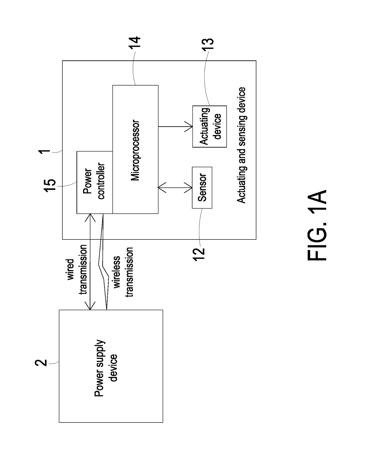
[0020]FIG. 1A schematically illustrates the architecture of a driving system for an actuating and sensing module according to the present disclosure. As shown in FIG. 1A, the driving system for the actuating and sensing module includes an actuating and sensing device 1 and a power supply device 2. The actuating and sensing device 1 includes at least one sensor 12, at least one actuating device 13, a microprocessor 14 and a power controller 15. The power controller 15 receives an energy and transfers the energy to enable the sensor 12 and the actuating device 13.

[0021]An example of the sensor 12 includes but is not limited to a temperature sensor, a volatile organic compound sensor (e.g., a sensor for measuring formaldehyde or ammonia gas), a particulate sensor (e.g., a PM2.5 particle sensor), a carbon monoxide sensor, a carbon dioxide sensor, an oxygen sensor, an ozone sensor, any other appropriate gas sensor, a humidity sensor, a water content sensor, a substance sensor (e.g., a se...

second embodiment

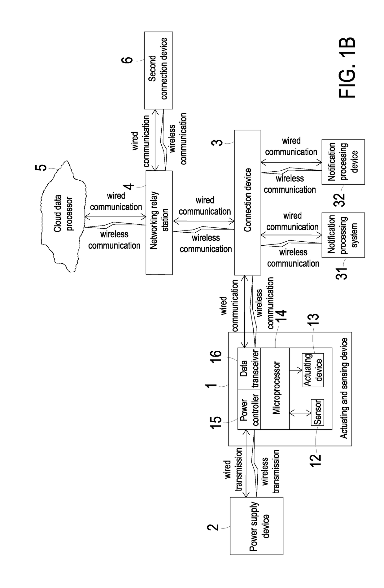
[0026]FIG. 1B schematically illustrates the architecture of a driving system for an actuating and sensing module according to the present disclosure. As shown in FIG. 1B, the actuating and sensing device 1 of the driving system for the actuating and sensing module further includes a data transceiver 16, and the data transceiver16 is a device for receiving or transmitting data. The driving system for the actuating and sensing module further includes a connection device 3. In this embodiment, the microprocessor 14 of the actuating and sensing device 1 is used for processing and converting the monitored data transmitted from the sensor 12 into an output data. The data transceiver 16 may receive and transmit the output data to the connection device 3. After that, the connection device 3 may display or store the information carried in the output data, or transfer the information carried in the output data to a storage device (not shown) of the connection device 3 to be stored and process...


PUM

PropertyMeasurementUnit
energyaaaaaaaaaa
lengthaaaaaaaaaa
response timeaaaaaaaaaa

Abstract

A driving system for an actuating and sensing module includes an actuating and sensing device and a power supply device. The actuating and sensing device includes a sensor, an actuating device, a microprocessor, and a power controller. The power supply device transfers an energy to the power controller, thereby enabling the sensor and the actuating device.

Description

FIELD OF THE INVENTION[0001]The present disclosure relates to an environmental monitoring system for an actuating and sensing module, and more particularly to a driving system for an actuating and sensing module.BACKGROUND OF THE INVENTION[0002]Nowadays, people pay much attention to the devices and methods of monitoring the air quality in the environment. For example, it is important to monitor carbon monoxide, carbon dioxide, volatile organic compounds (VOC), PM2.5, and so on. The exposure of these gases in the environment will cause human health problems or even harm the life. Therefore, it is important for every country to develop and implement the environmental monitoring technology.[0003]Generally, it is feasible to use an ambient sensor to monitor the air quality in the environment. If the ambient sensor is capable of immediately providing people with the monitored information relating to the environment for caution, it may help people escape or prevent from injuries and influ...

Claims


Application Information

Patent Timeline
Patent Type & Authority Applications(United States)
IPC IPC(8): G01N1/22G01N33/00
CPCG01N1/2273G01N33/0011F04B43/046F04D33/00
Inventor MOU, HAO-JANHUANG, CHI-FENGHAN, YUNG-LUNGTSAI, CHANG-YENLEE, WEI-MINGCHEN, HSUAN-KAI
Owner MICROJET TECH
Learn More