
Application of polymer thermofoil to metal substrate

a technology of thermofoil and metal substrate, applied in the direction of coatings, layered products, chemistry apparatus and processes, etc., can solve the problems of difficult thermofoil application, inability to place these parts in the vacuum membrane press during the thermofoil application process, and inability to work with thermofoil on metal substrates. , to achieve the effect of ensuring the stability of the metal substrate, and excellent strength

Pending Publication Date: 2019-02-14
MIDMARK
View PDF5 Cites 0 Cited by
  • Summary
  • Abstract
  • Description
  • Claims
  • Application Information

AI Technical Summary

Benefits of technology

The patent text describes the use of thermofoil to create a wood-like appearance on fiberboard, which can be used to create cabinetry that looks like real wood without the high cost. The text also mentions that while metal is a great option for durability, its appearance can be limited to certain finishes. The technical effect of this patent is to offer a solution that allows for the metal body of the cabinet to be finished in more aesthetically pleasing finishes like faux wood grain or other finishes that match the cabinet doors.

Problems solved by technology

In contrast to wood-based substrates, working with thermofoil on metal substrates can be difficult for a number of reasons.
Often, pre-formed or pre-machined metal substrates are shaped in such a way that it is impossible to apply thermofoil to the part, or even if thermofoil can be applied to the part, it is simply not practical to place these parts in the vacuum membrane press during the thermofoil application process.
In addition, because these parts are metal, they often have sharp edges that can easily damage the vacuum membrane press during thermofoil application.
Because of these and other issues, thermofoil has historically not been used in applications in which it is applied to a metal substrate.
However, in certain applications the aesthetic appeal of steel cabinets finished in a single color paint or powder coat finish is not ideal.
While such an arrangement offers clear advantages, it does not fully eliminate aesthetic concerns, as the metal body of the cabinet is still unable to be offered in more aesthetically pleasing finishes such as faux wood grain or other finish selected to match accompanying cabinet doors.

Method used


Image

  • Application of polymer thermofoil to metal substrate
  • Application of polymer thermofoil to metal substrate

Examples


Embodiment Construction

[0010]The present invention is directed to a novel process for applying thermofoil to a metal substrate. More specifically, the present invention is directed to application of thermofoil to a painted, or coated, metal substrate.

[0011]While the present invention is primarily focused on the use of thermofoil-coated metal substrates in cabinetry, it will be understood that the methods described herein can also be used in non-cabinetry applications, such as in automotive accessories, other household accessories, or other instances in which a thermofoil-coated metal substrate would beneficially provide both aesthetics and durability.

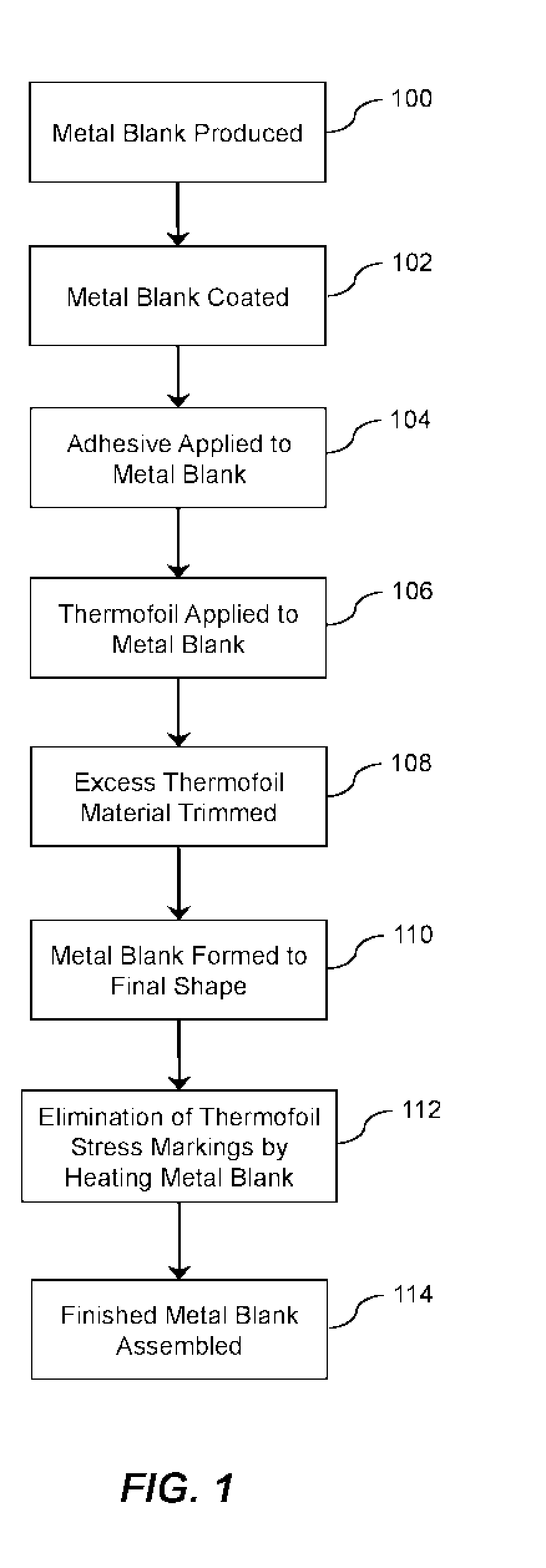
[0012]Turning now to a description of FIG. 1, there is shown a flow chart depicting one preferred method of performing the process of the present invention. Each of the steps involved in the flow chart will be described in greater detail below, including variations of these steps that also fall within the scope of the present invention.

[0013]In box 100, an in...


PUM

PropertyMeasurementUnit
shapeaaaaaaaaaa
surface finishaaaaaaaaaa
vacuum pressureaaaaaaaaaa

Abstract

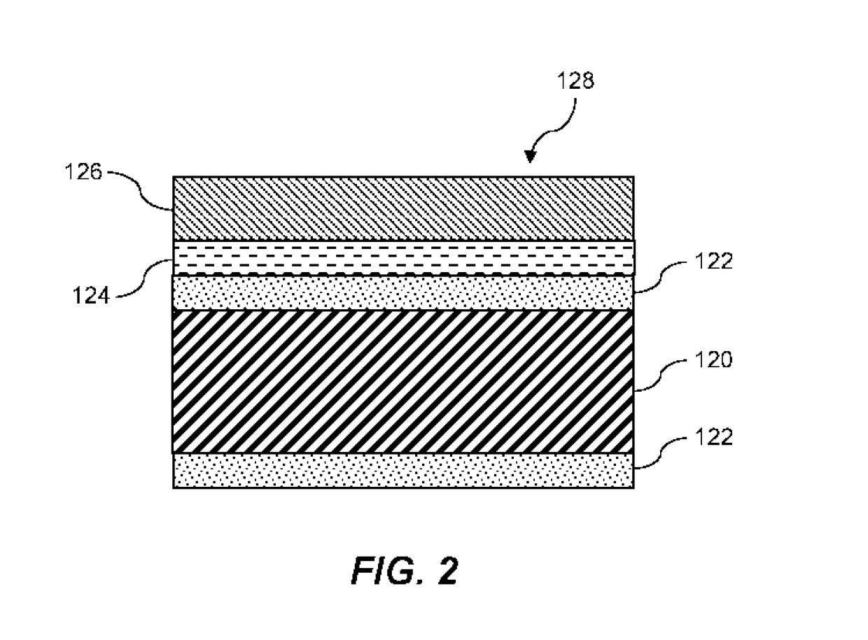
The present invention is directed to a novel method for application of polymer thermofoil to a metal substrate. The method involves first coating a metal substrate with an oxidation-preventing or oxidation-limiting coating, then adhering a polymer thermofoil to the metal substrate. After application of the thermofoil, the metal substrate can be formed to the final shape. The method is advantageous in that it allows one to efficiently manufacture metal objects in a variety of aesthetically pleasing surface finishes.

Description

CLAIM OF PRIORITY[0001]This application claims priority to U.S. 62 / 099,163.BACKGROUND AND BRIEF SUMMARY OF THE INVENTION[0002]The present invention is directed to a novel method for making metal cabinetry and other metal objects more aesthetically pleasing to the end user. More particularly, the present invention involves the application of thermofoil surface finish to metal substrate as will be described in greater detail below.[0003]Thermofoil surface finish is well known in the cabinetry industry, so will not be discussed in detail herein. However, briefly stated, thermofoil is a thin polymeric material (commonly a plasticized polyvinyl chloride) that is thermoformed, under vacuum pressure to a substrate, thus giving the substrate a durable top coat or surface finish. Thermofoil comes in a number of finishes, including high and low sheen, metallic-like finishes and faux wood grain finishes. The process of applying thermofoil generally involves the steps of (1) preparing the subst...

Claims


Application Information

Patent Timeline
Patent Type & Authority Applications(United States)
IPC IPC(8): B32B37/12B32B37/10B29C65/00B29C51/08
CPCB32B2327/06B32B37/10B29C66/742B29C51/082B32B37/1207B21D22/00B29C51/16B29C65/48B29C66/034B29C66/1122B29C66/47B29C66/71B29C66/7392B29K2027/06B29C69/007B32B38/0012B32B2037/1215B32B2255/06B29K2105/0097B29K2305/00B29L2009/001
Inventor STRAIT, SCOTTHEITKAMP, ALANRIEMAN, DUANESTEINBRUNNER, LINDA
Owner MIDMARK
Learn More