

Power plant and method of controlling same
a technology of power generator and working fluid, applied in the direction of electric storage system, machines/engines, mechanical equipment, etc., can solve the problems of excessive temperature and pressure of working fluid, damage to electric generators, etc., and achieve the effect of avoiding damag
- Summary
- Abstract
- Description
- Claims
- Application Information
AI Technical Summary
Benefits of technology
Problems solved by technology
Method used
Image

Examples
first embodiment
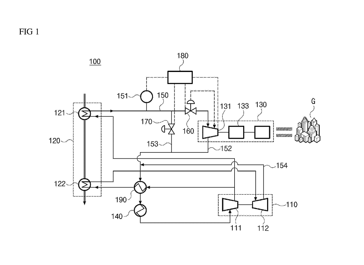
[0030]Referring to FIG. 1, a power plant 100 according to the present disclosure is a system to generate electricity using a working fluid. The power plant 100 comprises a pump 110 that compresses a working fluid and sends the resulting compressed working fluid, a heat exchanger apparatus or a heat exchanger 120 that heats the working fluid by using an external heat source, a power turbine generator 130 that generates electricity by using the working fluid, a condenser 140 that cools and condenses the working fluid, a working fluid supply line 150 that provides a flow path for the working fluid so as to be conveyed to the power turbine generator 130, a pressure sensor 151 that measures the pressure of the working fluid, a working fluid recovery line 152 that conveys the working fluid to the pump 110, a bypass line 153 that allows a portion of the working fluid destined for the power turbine generator 130 to bypass the power turbine generator 130, a first and second control valves 16...
second embodiment
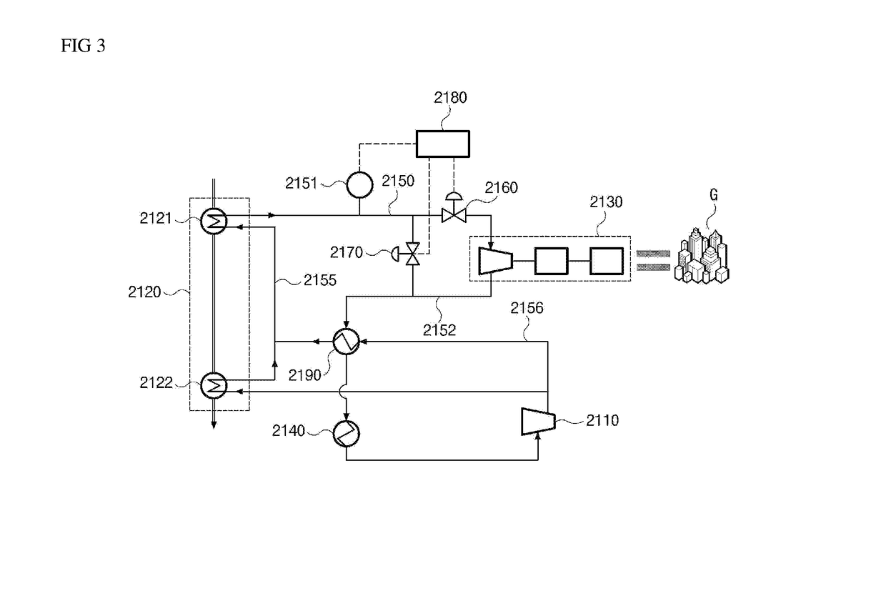
[0065]FIG. 3 is a schematic diagram illustrating a power plant according to the present disclosure.
[0066]Referring to FIG. 3, according to the second embodiment of the present disclosure, a power plant comprises a pump 2110, a heat exchanger apparatus 2120, a power turbine generator 2130, a condenser 2140, a working fluid supply line 2150, a pressure sensor 2151, a working fluid recovery line 2152, a bypass line allowing a portion of the working fluid to bypass the power turbine generator 2130, a first and second control valves 2160 and 2170, and a controller 2180 for controlling the first and second control valves 2160 and 2170.
[0067]The power plant according to the second embodiment of the present disclosure is established by modifying the configuration of the heat exchanger apparatus of the power plant according to the first embodiment described above.
[0068]Among the components of the power plant according to the second embodiment of the present disclosure, a description of the s...
third embodiment
[0075]FIG. 4 is a schematic diagram illustrating a power plant according to the present disclosure.
[0076]Referring to FIG. 4, the power plant according to the third embodiment of the present disclosure comprises a pump 3110, a heat exchanger apparatus 3120, a power turbine generator 3130, a condenser 3140, a working fluid supply line 3150, a pressure sensor 3151, a working fluid recovery line 3152, a bypass line 3153 allowing a portion of the working fluid to bypass the power turbine generator 3130, a first and second control valves 3160 and 3170, and a controller 3180 for controlling the first and second control valves 3160 and 3170.
[0077]Among the components of the power plant according to the third embodiment of the present disclosure, a description of the same components as those of the second embodiment described above will be omitted and only components that are different from those of the second embodiment will be described below.
[0078]The power plant according to the third e...
PUM
 Abstract
Description
Claims
Application Information