System for reducing localised fatty masses by means of cold application, applicator for such a system and non-invasive treatment method for reducing fats by means of cold application

a technology of localized fatty mass and cold application, which is applied in the direction of contraceptive devices, therapeutic cooling, heating, etc., can solve the problems of large number of working hours, complex design of cryolipolysis devices of this type, and difficult to meet the needs of patients, so as to improve the adaptation of the applicator and simplify the production of the device. , the effect of reducing fa

Inactive Publication Date: 2019-02-21
DELEO LTD
View PDF0 Cites 36 Cited by
  • Summary
  • Abstract
  • Description
  • Claims
  • Application Information

AI Technical Summary

Benefits of technology

[0013]The aim of the present invention is in particular to eliminate these disadvantages, and its objective is in particular to simplify the production of a device designed to carry out non-invasive treatment for reducing fats by means of cold application, whilst permitting better adaptation of an applicator to the morphology of the human body.

Problems solved by technology

Thus, the known cryolipolysis devices are particularly complex to produce, in that they require the central unit to be connected electronically and electrically to the applicators in order to trigger and control the cooling elements.
Thus, the design of a device of this type is complex to produce because of the large number of elements necessary for the manufacture of the applicators.
Also, the assembly of the applicators of the devices according to the prior art requires a qualified workforce, and a large number of working hours is necessary in order to accommodate all the aforementioned elements inside the housing of the applicator of such devices.
This safety system is therefore complex, and increases the number of electronic elements necessary in order to ensure adequate safety.
In addition, since the applicator must accommodate a plurality of temperature sensors as well as an electronic board for the operation of these sensors, its size cannot easily be reduced.
Also, it is particularly difficult to design devices comprising specific applicators for complex anatomical areas, such as very small wads in particular.

Method used


Image

  • System for reducing localised fatty masses by means of cold application, applicator for such a system and non-invasive treatment method for reducing fats by means of cold application
  • System for reducing localised fatty masses by means of cold application, applicator for such a system and non-invasive treatment method for reducing fats by means of cold application

Examples


first embodiment

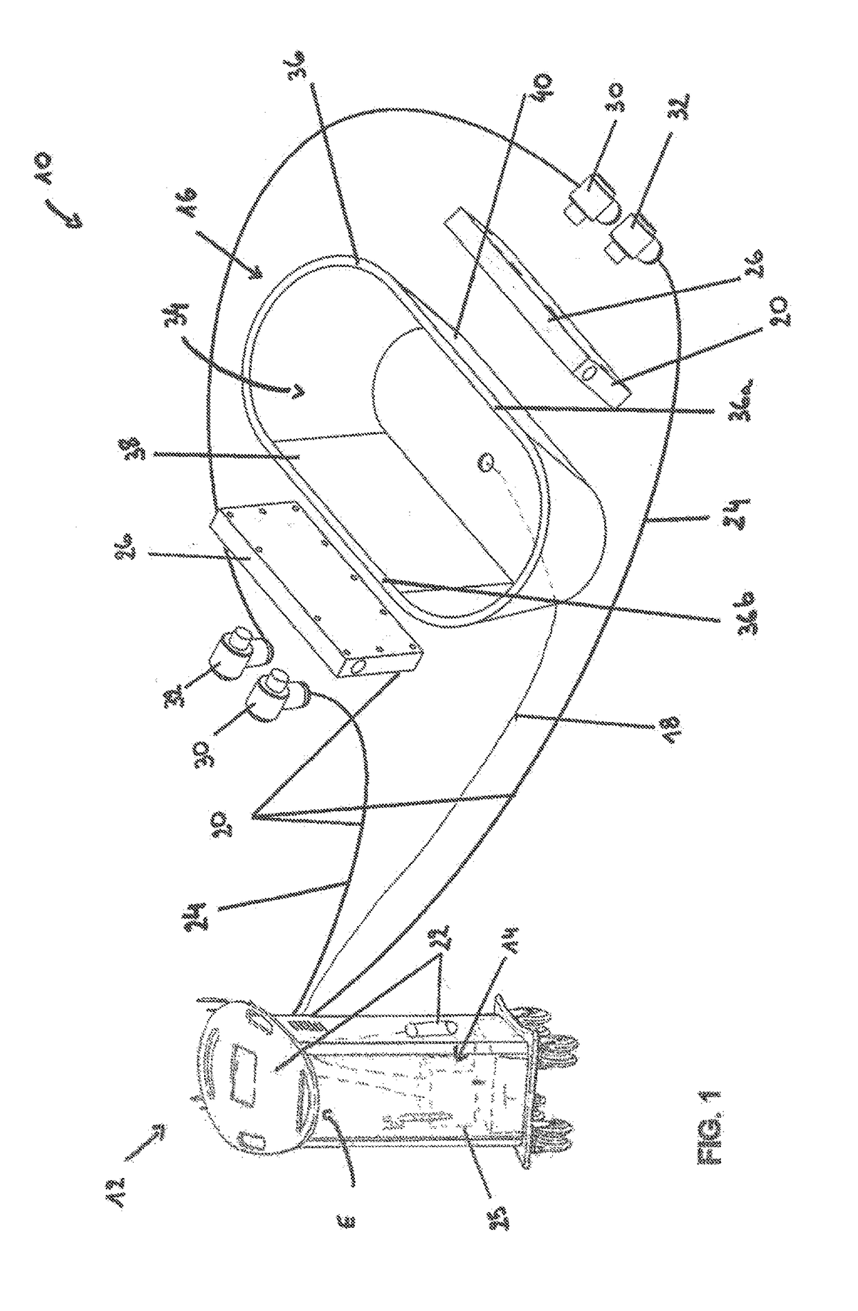
[0069]In this case, as illustrated in FIG. 1, and the transport device comprises two main ducts 24 which extend from the cooling device 14, and more specifically from the central unit 12, to the applicator 16. The main ducts 24 are designed to convey the fluid cooled by the cooling device 14 to the applicator 16. As represented in FIG. 1, the transport device 20 also comprises two header tanks 26. The main ducts 24 are connected to the applicator by means of two header tanks 26 which permit thermal transmission from the fluid to the applicator 16.

[0070]In variant embodiments not represented, the transport device can comprise one or more than two main ducts. In addition, the transport device can comprise one or a plurality of boxes, for example 3 or 4 header tanks.

[0071]The header tanks 26 are connected directly to the applicator 16.

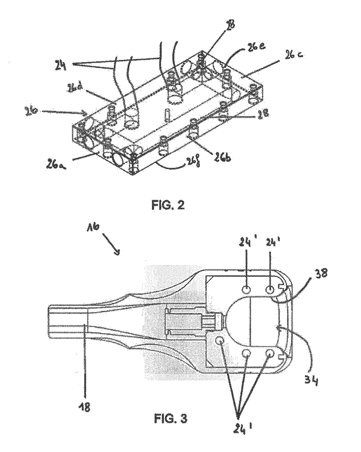
[0072]FIG. 2 illustrates according to a view in perspective a header tank 26 in FIG. 1. The header tank 26 comprises an inner cooling duct 28 for circul...

second embodiment

[0078]According to the transport device 20 illustrated in particular partly in FIG. 3, a portion of the transport device is integrated in the wall of the cavity, and substantially surrounds the cavity. In this case, the transport device 20 comprises one or a plurality of main ducts 24 which are extended by secondary ducts 24′. The secondary ducts 24′, as illustrated in FIG. 3, are accommodated in the wall 36 of the applicator 16. In other words, the secondary ducts 24′ are integrated in the wall 36 of the applicator 16. The fluid obtained from the main duct(s) also circulates in the secondary ducts 24′, such as to cool the inner surface 38. As represented in FIG. 3, a plurality of secondary ducts are provided. However, according to variant embodiments, a single secondary duct can be provided, which is wound around the cavity 34. The applicator 16 as represented in FIG. 3 has a form slightly different from that of the applicator 16 represented in FIG. 1. In this case, the form of the...


PUM


Abstract

A non-invasive treatment method for reducing fats using a system (10) for performing a non-invasive treatment for reducing fats by cold application. The system (10) includes a central unit (12), a cooling device (14) for cooling a fluid, at least one applicator (16) for performing a non-invasive localized treatment of the fats by cold application, including a cavity, a suction conduit (18) opening up into the cavity (34) and arranged so as to suck up a bead in the cavity (34), and a transport device (20) for conducting the fluid from the central unit inside the applicator. The wall of the cavity (34) is suitable for being indirectly cooled by the cooling device and the cooling device (14) is arranged at a distance from the applicator.

Description

FIELD OF THE INVENTION[0001]The present invention relates to the field of medical devices for reducing localized fatty masses by means of cold application, and in particular to a so-called “cryolipolysis” device (also known by the term “Cryolipolysis®”) which permits apoptosis of the localized adipocytes of a patient.BACKGROUND OF THE INVENTION[0002]Document US 2003 / 0220674 in particular discloses a medical device for reducing localized fatty masses by means of cold application.[0003]This type of medical device is designed to reduce the fatty mass by using the so-called Cryolipolysis® method which is well known to persons skilled in the art. The main steps of a cryolipolysis treatment are as follows: the area of the skin to be treated is covered with a cloth previously impregnated with a cryoprotective gel, then the applicator of the machine is placed on this cloth. The machine progressively sucks up the wad of fat into a cavity in the applicator and cools it.[0004]The duration of t...

Claims


Application Information

Patent Timeline
Patent Type & Authority Applications(United States)
IPC IPC(8): A61F7/02A61F7/10
CPCA61F7/02A61F7/10A61F2007/0056A61F2007/0095A61F2007/0246A61F2007/0052A61F2007/029A61F2007/0239
Inventor SAMSON, HERBERT
Owner DELEO LTD
Why Eureka
Try Eureka