
Drainage Catheter With Retractable Internal Drains

a technology of internal drain and draining catheter, which is applied in the direction of catheter, wound drain, guide wire, etc., can solve the problems of frequent blockage of the catheter, unfavorable and excessive body fluid accumulation, etc., to achieve the effect of convenient insertion and placement of the primary catheter in the subj

Active Publication Date: 2019-02-21
KING SAUD UNIVERSITY
View PDF3 Cites 12 Cited by
  • Summary
  • Abstract
  • Description
  • Claims
  • Application Information

AI Technical Summary

Benefits of technology

This patent describes a device that can be used to facilitate the insertion and location of a primary catheter in a subject. When the drains are retracted, the device provides a smooth transition for easy insertion. When the drains are deployed, they expand and create a larger area for drainage and irrigation. The device also has multiple fluid flow paths and locations, making it easier to manage and control the flow of fluids. Overall, this device improves the efficiency and effectiveness of medical procedures.

Problems solved by technology

Excessive body fluid can accumulate causing unwanted symptoms or complications.
A problem facing most body fluid drainage catheters is frequent blockage of the catheter.
However, on many occasions these procedures fail and replacement of the catheter becomes necessary.
Catheter replacement can be simple, though uncomfortable, such as in the case of urinary catheter replacement, or it can be complex and require an operative procedure, such as in the cases of cerebrospinal fluid shunt replacement or peritoneal dialysis catheter replacement.
Drainage catheter blockage is frequently attributed to clogged catheter pores or clogged drainage lumens.
Another challenge with drainage and irrigation catheterization is that in many instances multiple or larger fluid-filled cavities or areas need to be drained or washed at the same time.
The foregoing multi-drain catheters suffer from a variety of problems and shortcomings.
For example, because the proposed catheters have multiple distal drain ducts and drain tubes fixed in a permanently deployed state they occupy a relatively large volume of space.
This makes insertion in a subject difficult.
Insertion through an incision is likely to require a relatively large incision, which can be more problematic for the subject.
Alternatively, insertion through a naturally occurring tract of a subject may be difficult or impossible due to the length and narrowness of the tract.
For example, it may be difficult or impossible to insert such a catheter into the stomach of a subject through the subject's nose or mouth tract, as in the case of a nasogastric tube, or through a subject's urethra, as in the case of a Foley catheter.
Further, such a catheter is likely incapable of deep percutaneous insertion as the plurality of permanently deployed distal drain tubes is likely to create significant friction while advancing through long narrow tracts and to encounter obstructions when passing through a subject's tissues.
Although the proposed catheter addresses the insertion difficulties of other multi-tube catheters by enclosing the plurality of tube structures in a sheath during insertion, the plurality of tube structures are joined at their distal ends and the catheter is therefore incapable of providing multiple spaced apart drain locations or locating drain tubes in different spaces like the other proposed multi-tube catheters.
Moreover, deployment of the distal tube structures in an “open basket” configuration creates a risk of entangling or entrapping a subject's internal organs or a section of bowel during or after deployment.
However, because the catheter has only a single internal drain it is only capable of providing a single point of drainage at a single location.
While the proposed ventricular catheter addresses the insertion problems of other prior art multi-drain catheters by reducing the space occupied by the multiple distal lumens, it provides only very limited drainage surface area and lacks the ability to provide multiple spaced apart drainage locations like other proposed multi-drain catheters.
However, these proposals also suffer from various problems and shortcomings.
Additionally, using an insertion sheath still may not adequately address the problems that attend inserting a multi-drain catheter having a plurality of distal drain tubes.
The distal tubes of such catheters may still occupy so much space that they encounter excess friction or obstructions even while passing through a sheath.
Such catheters with smaller internal drain lumens may even bend, making insertion even more difficult, particularly when the insertion length is long and / or the insertion tract has twists and turns.
Still further, none of the proposals address how to insert and direct the distal drain tubes of a multi-drain catheter within a sheath into different areas to be drained, or how to advance the drain tubes further or direct them into different locations once the sheath is removed.
However, all of these designs still present the same insertion problems as the multi-drain catheter designs.
Moreover, they are only capable of draining a single area at a time and cannot provide multiple drain sites in different locations simultaneously and without multiple insertions.
However, none of the proposed designs has successfully solved the problems of catheter clogging by fluid borne debris and the coating of indwelling catheters by endogenous tissue.
Moreover, the presence of fabric or netted materials can harbor bacteria and lead to infection, and the inclusion of padding material can require a larger entry wound for insertion.
From the foregoing, it can be seen that while a variety of catheter designs have been proposed, the disclosed catheters remain subject to various problems and shortcomings.

Method used


Image

  • Drainage Catheter With Retractable Internal Drains
  • Drainage Catheter With Retractable Internal Drains
  • Drainage Catheter With Retractable Internal Drains

Examples


Embodiment Construction

A. Overview.

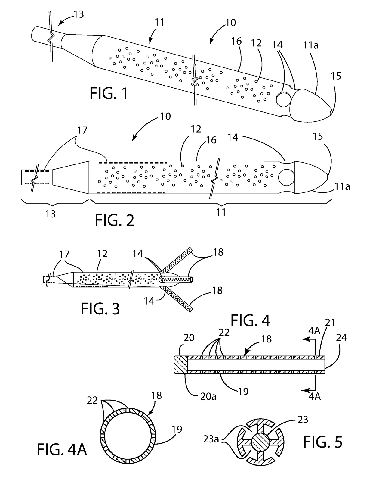
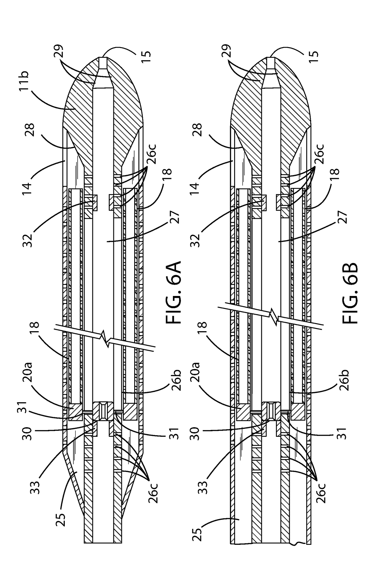
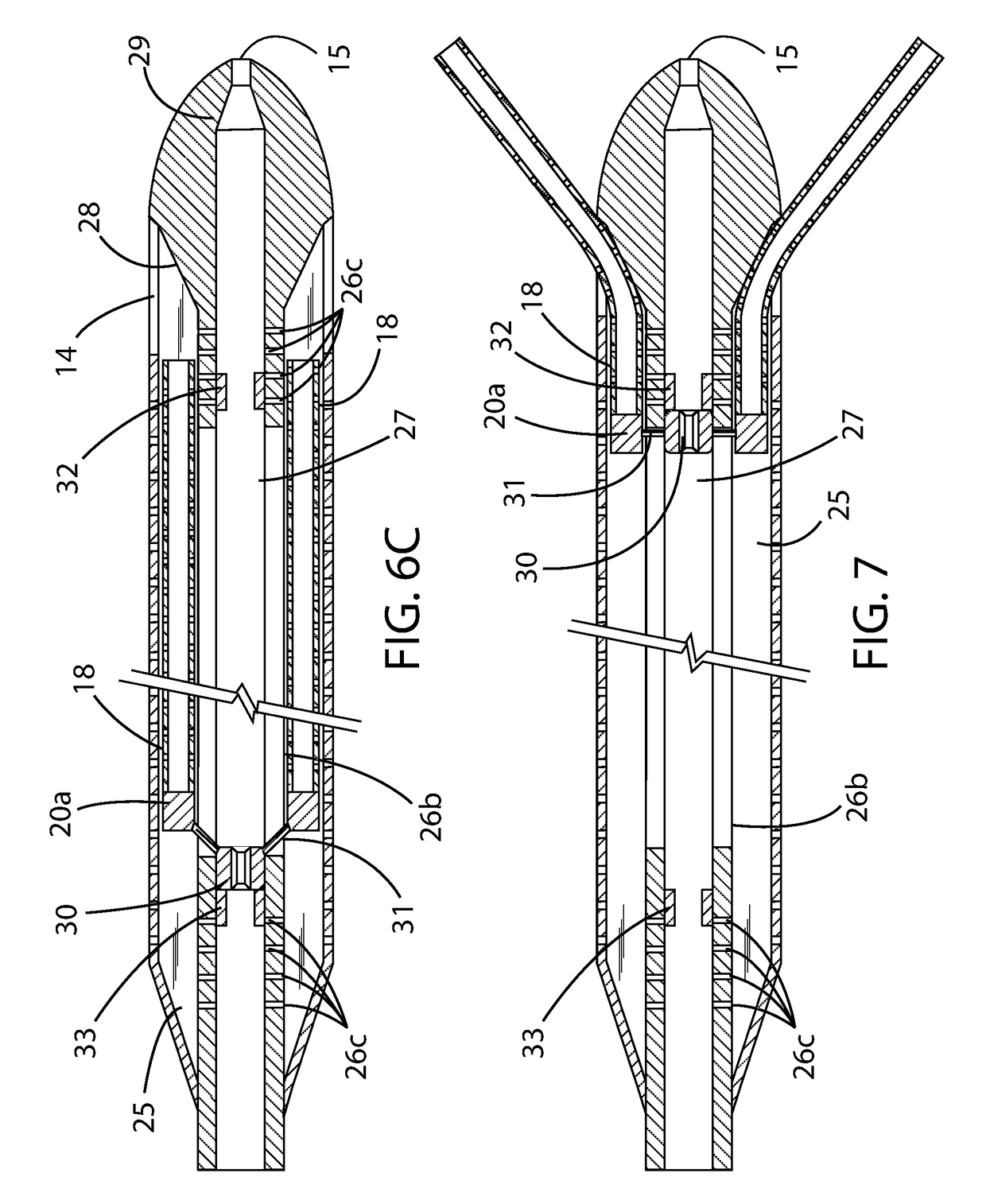
[0052]An example drainage catheter with retractable internal drains generally includes a primary catheter, a plurality of internal retractable drains, a central connecting piece, and a stylet adapted to engage with the central connecting piece. The primary catheter comprises proximal and distal ends and has a plurality of drain openings therebetween. A plurality of internal drain ports are formed in the distal end of the catheter body. A central track and a plurality of peripheral tracks within the primary catheter define a plurality of lumens which are adapted to conduct fluid flow between the proximal and distal ends of the catheter for drainage and irrigation.

[0053]An internal retractable drain is disposed within each of the peripheral tracks. During insertion of the primary catheter into a subject, the internal drains are in a retracted state within the peripheral tracks. After insertion, the internal retractable drains can be repositioned in a deployed state in whic...


PUM


Abstract

A drainage catheter with retractable internal drains for fluid drainage and irrigation. The drainage catheter with retractable internal drains generally includes a primary catheter for insertion within a subject, a lumen within the primary catheter for conducting fluid flow between a source of fluid drainage or irrigation and the subject, and a plurality of selectively retractable and deployable drains in fluid communication with the lumen. Retraction and deployment of the drains within a subject is accomplished remotely via a specially shaped stylet and common drain connector within the primary catheter. The plurality of drains are enclosed within the primary catheter in the retracted state and extend radially outwardly from the primary catheter in the deployed state. In the retracted state, insertion and location of the primary catheter in a subject are facilitated. In the deployed state, expanded and improved drainage and irrigation area and a plurality of fluid flow paths and locations are provided.

Description

CROSS REFERENCE TO RELATED APPLICATIONS[0001]Not applicable to this application.STATEMENT REGARDING FEDERALLY SPONSORED RESEARCH OR DEVELOPMENT[0002]Not applicable to this application.BACKGROUNDField[0003]Example embodiments in general relate to a Drainage Catheter With Retractable Internal Drains for providing improved fluid drainage and irrigation particularly for medical applications.Related Art[0004]Any discussion of the related art throughout the specification should in no way be considered as an admission that such related art is widely known or forms part of common general knowledge in the field.[0005]Draining fluid from the body of a subject may be necessary for treating various illnesses. Excessive body fluid can accumulate causing unwanted symptoms or complications. For example, excess accumulation of cerebrospinal fluid can lead to hydrocephalus, excess accumulation of plural fluid can cause pleural effusion, and excess accumulation of peritoneal fluid can cause ascites. ...

Claims


Application Information

Patent Timeline
IPC IPC(8): A61M3/02A61M27/00A61M25/00A61M1/28
CPCA61M3/0283A61M27/00A61M25/007A61M25/0026A61M2205/583A61M1/285A61M25/0102A61M25/09A61M27/006A61M25/0071A61M25/0082A61M2025/0096A61M1/85A61M2025/0175
Inventor AL-JAZAERI, AYMAN H.
Owner KING SAUD UNIVERSITY
Learn More