
High temperature and pressure liquid degassing systems

a technology of liquid degassing and high temperature, applied in liquid degasification, lighting and heating apparatus, separation processes, etc., can solve the problems of fuel deoxygenation, high temperature fuel, and inability to do both

Inactive Publication Date: 2019-02-21
HAMILTON SUNDSTRAND CORP
View PDF0 Cites 6 Cited by
  • Summary
  • Abstract
  • Description
  • Claims
  • Application Information

AI Technical Summary

Benefits of technology

The patent describes a hollow fiber cartridge for a hollow fiber membrane degassing system, which includes a bundle of selectively permeable membrane tubes and tube sheets for mounting the tubes within a housing. The tube sheets are made of one of several materials, such as Fluorosilicone, Fluorocarbon, or Polysulfide. The system allows a fluid to flow through the tubes while a gas permeates through the walls of the tubes and into the fluid flow path, resulting in efficient removal of gas from the fluid. A degassing device comprising the hollow fiber cartridge and a housing is also described. The technical effects of the invention include improved gas removal efficiency, reduced pressure drop, and increased durability of the degassing system.

Problems solved by technology

Increased thermal loads and decreased fuel flows anticipated for next generation aircraft will cause higher temperature fuel considering fuel is used as a heat sink.
Although hollow-fiber modules have been used extensively for gas separation applications, fuel deoxygenation on board an aircraft presents unique problems related to sealing the membrane against fuel leaks, for example.
In particular, existing hollow-fiber modules with proven performance in hydrocarbon liquid degassing can operate at either ambient pressure and elevated temperatures or at elevated pressures and ambient temperatures, but they cannot do both because existing system may leak.
Part of the reason is that the techniques currently used to seal the hollow fiber bundle against hot fuel pressure are inadequate for long-term performance in hot jet fuel under pressure.

Method used


Image

  • High temperature and pressure liquid degassing systems
  • High temperature and pressure liquid degassing systems

Examples


Embodiment Construction

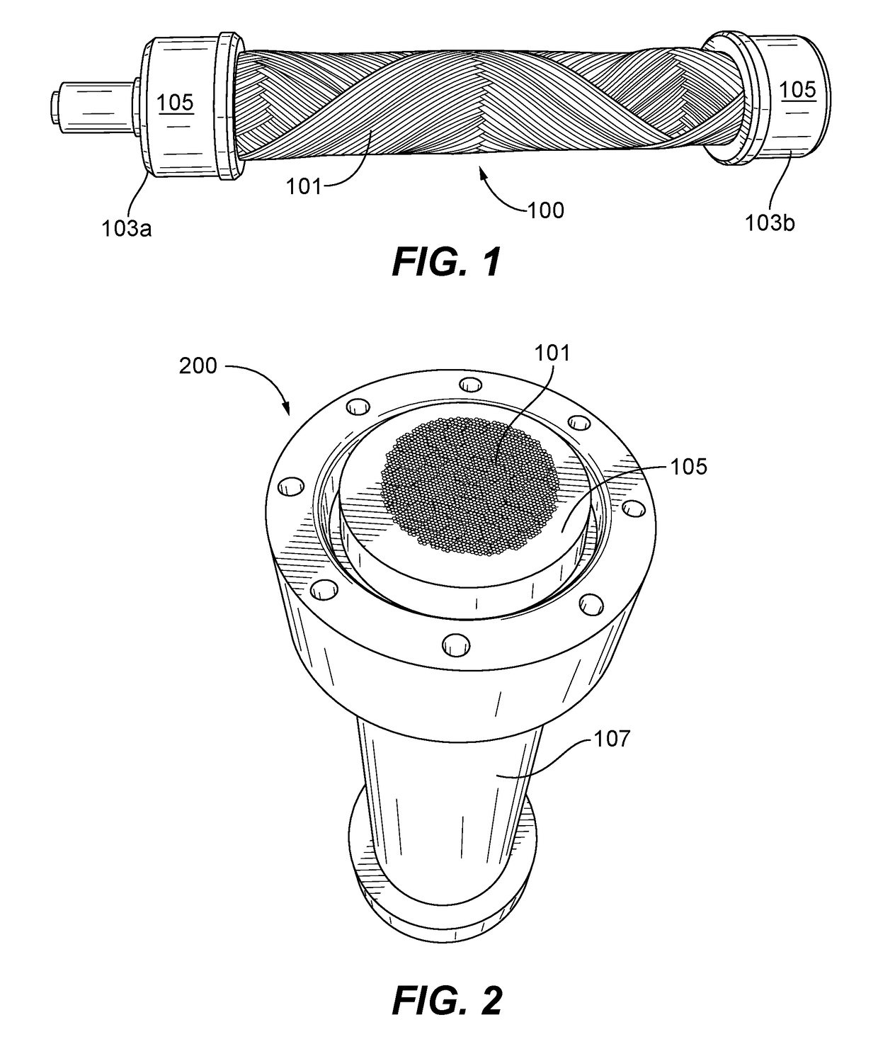
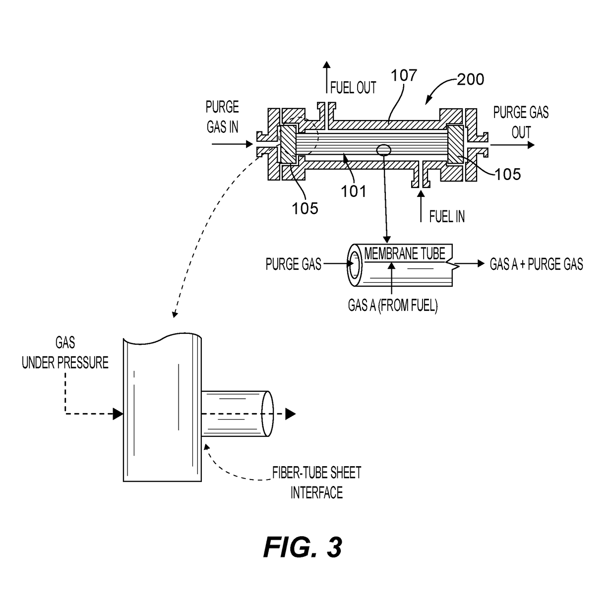
[0015]Reference will now be made to the drawings wherein like reference numerals identify similar structural features or aspects of the subject disclosure. For purposes of explanation and illustration, and not limitation, an illustrative view of an embodiment of a cartridge in accordance with the disclosure is shown in FIG. 1 and is designated generally by reference character 100. Other embodiments and / or aspects of this disclosure are shown in FIGS. 2 and 3. The systems and methods described herein can be used to handle high heat and pressure in degassing systems (e.g., for aircraft fuel deoxygenation systems), for example.

[0016]Referring to FIG. 1, an embodiment of a hollow fiber cartridge 100 for a hollow fiber membrane degassing system (e.g., as shown in FIGS. 2 and 3) includes a tube bundle 101 of selectively permeable membrane tubes having inner channels. The bundle 100 includes two ends 103a, 103b and a tube sheet 105 at each end of the tube bundle 101 binding the ends of tub...


PUM

PropertyMeasurementUnit
permeableaaaaaaaaaa
densityaaaaaaaaaa
selectively permeableaaaaaaaaaa

Abstract

A hollow fiber cartridge for a hollow fiber membrane degassing system, comprising a tube bundle of selectively permeable membrane tubes having inner channels, the bundle including two ends, and a tube sheet at each end of the tube bundle binding the ends of tube bundle. The tube sheets are configured to mount the tube bundle within a housing of the degassing system. The tube sheets are comprised of one or more of at least one Fluorosilicone, at least one Fluorocarbon, or at least one Polysulfide.

Description

BACKGROUND1. Field[0001]The present disclosure relates to fluid degassing systems, more specifically to hollow fiber degassing systems (e.g., for fuel degassing such as deoxygenation).2. Description of Related Art[0002]Increased thermal loads and decreased fuel flows anticipated for next generation aircraft will cause higher temperature fuel considering fuel is used as a heat sink. However, when exposed to higher temperatures hydrocarbon fuels tend to form carbonaceous deposits due to the presence of dissolved oxygen, hence fuel stabilization will be required in order to meet performance and operability targets. The most efficient way to remove dissolved oxygen from fuel (the root cause of deposits) is by means of a membrane-based fuel deoxygenator.[0003]Certain deoxygenators include tubular membranes, known as “hollow-fiber” membrane modules. Although hollow-fiber modules have been used extensively for gas separation applications, fuel deoxygenation on board an aircraft presents un...

Claims


Application Information

Patent Timeline
Patent Type & Authority Applications(United States)
IPC IPC(8): B01D63/04B01D19/00B01D71/36B01D71/66B64D37/34C10G31/00C10L1/04
CPCB01D63/043B01D19/0031B01D71/36C10L2290/548B64D37/34C10G31/00C10L1/04B01D71/66B01D19/00B01D61/00B01D63/023F23K2900/05082
Inventor CORDATOS, HARALAMBOS
Owner HAMILTON SUNDSTRAND CORP
Learn More