Coupled quantum dot memristor

a quantum dot and coupled technology, applied in the field of coupled quantum dot memristor, can solve the problems of pinched hysteresis, or lissajous loop, no quantum-dot-based memristive device has been described up until now, and the use of a double quantum dot system as a memristive device has not been explored

Active Publication Date: 2019-02-21
OXFORD UNIV INNOVATION LTD
View PDF0 Cites 5 Cited by
  • Summary
  • Abstract
  • Description
  • Claims
  • Application Information

AI Technical Summary

Benefits of technology

[0036]Quantum dots have discrete energy spectra due to electron confinement in all three spatial directions. Coulomb repulsion between electrons in a quantum dot leads to an increasing energy cost for adding more electrons to the dot. In the following discussion it is assumed for simplicity that the energy space between discrete states and the Coulomb repulsion energy are large enough so that each quantum dot can be treated as a single-level system, i.e. each dot has only two states: empty or occupied with one electron. This simplified model allows the behaviour of a memristive system to be mathematically described relatively concisely. However, the present invention is not limited only to those memristive devices which are precisely described by such a model. Thus, the present invention also encompasses memristive devices in which at least one quantum dot (or both quantum dots) behaves as a two-level system.
[0056]Capacitive coupling and quantum-tunnelling-mediated coupling are both functions of distance, among other variables. The tunnelling current drops off exponentially with increasing distance (e.g. distance between a quantum dot and an electrode) whereas capacitive coupling varies linearly with distance, increasing linearly in strength as distance decreases. Preferably, where any two components are coupled to one another capacitively, there is negligible or zero coupling arising from quantum tunnelling between those components, i.e. the components are coupled only by capacitive coupling. Thus, where capacitive coupling between two components (such as an electrode and a quantum dot) is required, coupling via quantum tunnelling can easily be suppressed by choosing a distance between the two components at which the quantum tunnelling current is negligible or zero yet an appreciable degree of capacitive coupling is retained.

Problems solved by technology

This results in a pinched hysteresis, or Lissajous loop.
This effect (i.e. the fact that the device characteristics alter dramatically when the environment changes, e.g. via a change in the charge state in the immediate environment of the device) is frequently a frustration in experimental work.
However, no quantum-dot-based memristive devices have been described up until now.
While device geometries employing capacitive coupling between two quantum dots are known, the use of a double quantum dot system as a memristive device has not been explored to date and thus memristors based on capacitively-coupled double quantum dot systems have also been unknown before now.

Method used


Image

  • Coupled quantum dot memristor
  • Coupled quantum dot memristor
  • Coupled quantum dot memristor

Examples


example 1

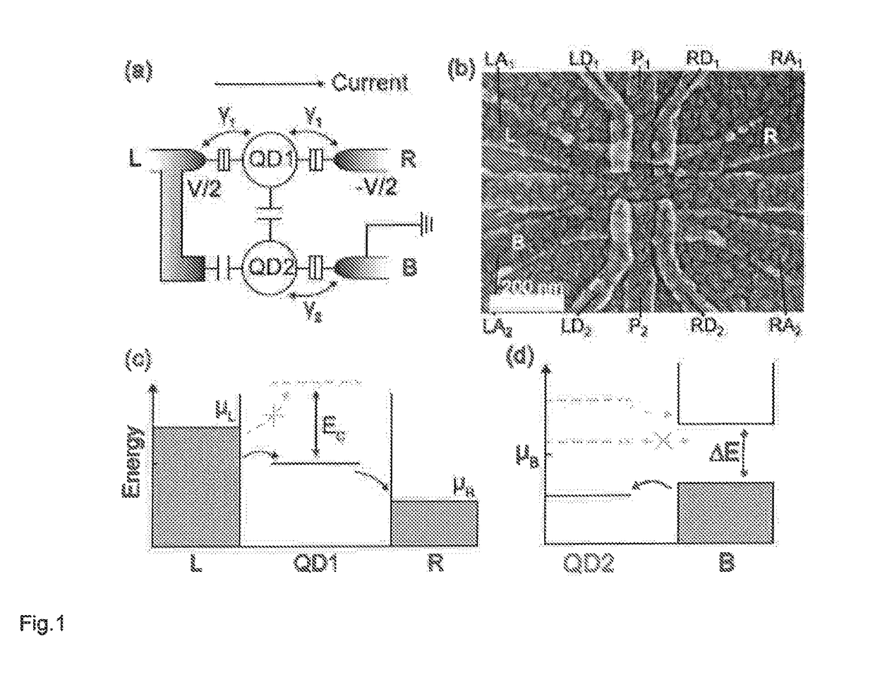
[0111]FIG. 1 illustrates a schematic of a quantum-dot memristive system according to the invention. As shown in FIG. 1(a), the device has two terminals: electrode-L and electrode-R. When a voltage V is applied on the device, electrochemical potentials in these two electrodes are respectively μL=|e|V / 2 and μR=−|e|V / 2. The two terminals are coupled to the quantum dot QD1 via tunnelling with the strength γ1, hence current can go through the device via QD1. The quantum dot QD2 is capacitively coupled to QD1 and to the electrode-L and is coupled to electrode-B via tunnelling with the strength γ2. The electrochemical potential in the electrode-B is μB=0.

[0112]FIG. 1(b) is an SEM image showing an experimental embodiment of a memristive system according to the invention. Three layers of aluminium gates were used to define a capacitively coupled pair of quantum dots in undoped silicon. The center-to-center distance between the two dots was ˜140 nm. Labels LA1, LD1, P1, RD1, RA1, LA2, LD2, P2...

example 2

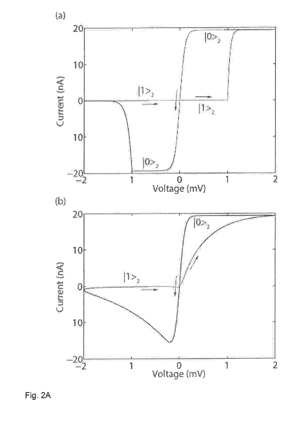
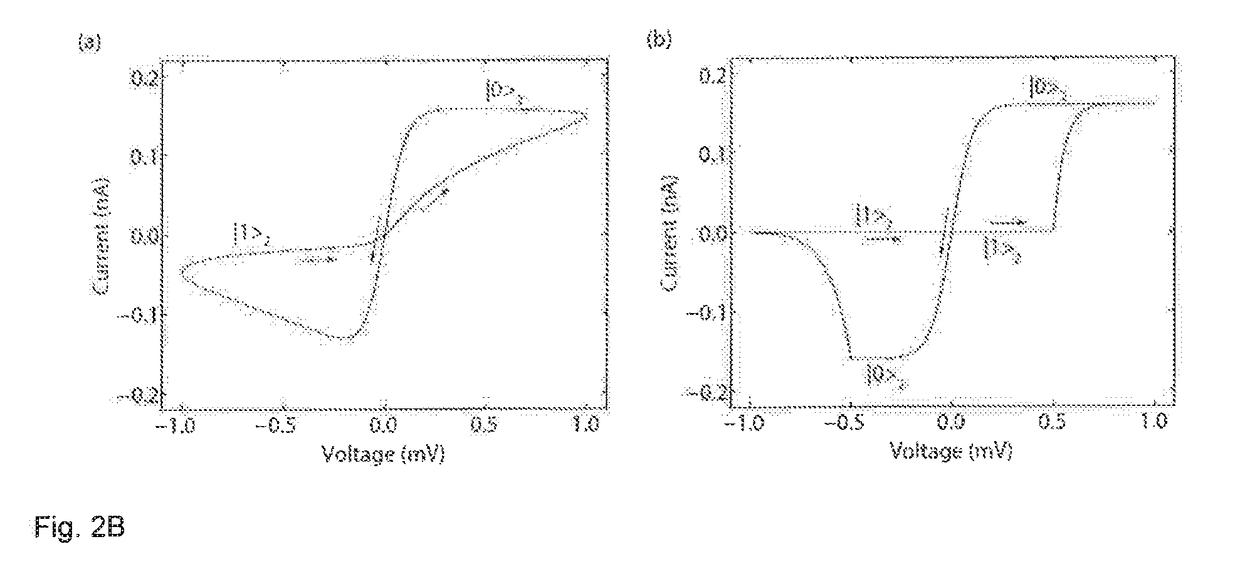
[0115]FIG. 2 illustrates simulated current-voltage curves of a quantum-dot memristive system according to the invention derived from a periodic voltage.

[0116]In the simulations shown in FIGS. 2A(a) and 2A(b), the voltage is in the form V(t)=VA cos ωt, where VA=2 meV and ω=2π×1 MHz. The temperature is T=0.3 K, the capacitive coupling between the two quantum dots QD1 and QD2 is EC=10 meV, the tunnelling coupling of QD1 is γ1=1 meV, and the lever arm of the electrode-L gating QD2 is 1. (The lever arm is the ratio between the shift of energy level E2 and the applied voltage, multiplied by the charge of an electron).

[0117]In the simulation shown in FIG. 2A(a), the electrode-B has an energy gap E=1 meV centered at the energy 0, and the tunnelling coupling of QD2 is {tilde over (γ)}2=1 μeV. When the energy level of QD2 is within the energy gap, i.e. V∈[−1 meV, 1 meV], QD2 is empty (|02) when the voltage is decreasing and occupied (|12) when the voltage is increasing.

[0118]In the simulation...

example 3

[0122]FIG. 3 illustrates quantum trajectory simulations of the instantaneous current in a quantum-dot memristive system according to the invention. Parameters are the same as described in Example 2.

[0123]FIG. 3(a) illustrates the voltage applied on the two terminals as a function of time.

[0124]FIGS. 3 (b) and (c) illustrate the current which is produced by the voltage illustrated in (a). The energy gap in the electrode-B is open (i.e. non-zero) in (b) and closed (i.e. zero) in (c). The instantaneous current (solid curve) is different from the average current (dashed curve) due to quantum jumps, which correspond to sudden changes of the instantaneous current.

[0125]FIG. 3(d) shows experimental data which was recorded for a working embodiment (as shown in FIG. 1(d) and described in further detail in Example 9). The solid curve is the instantaneous current and the dashed curve is the current averaged over 10 sweeps. Arrows indicate the position of abrupt current jumps. The jump position...


PUM


Abstract

The present disclosure relates to novel memristive devices, uses thereof, and processes for their preparation. In a first aspect, the disclosure provides a quantum memristor, including a first quantum dot (QD1) which is capacitively coupled to a second quantum dot (QD2), a source electrode, a drain electrode, and a bath electrode, wherein the source electrode and the drain electrode are coupled via quantum tunnelling to QD1 and the bath electrode is coupled via quantum tunnelling to QD2, and wherein QD2 is capacitively coupled to either the source electrode or the drain electrode.

Description

INTRODUCTION[0001]The present invention relates to novel memristive devices, uses thereof, and processes for their preparation.[0002]The devices of the invention have been made possible by the development of a new, generic, quantum-mechanical model of memristive systems which provides new insights into their behaviour. This model, described herein, opens the way to novel memristive devices which exploit behaviours explained for the first time by the new model. In particular, the new model has led to the surprising insight that certain behaviours which are often regarded as frustrations in experimental work may in fact be usefully harnessed as the basis of memristive function.BACKGROUND[0003]Memristive Systems are Generalisations of Memristors, which are Resistors with Memory.[0004]Resistors, capacitors and inductors are the three fundamental circuit elements that are familiar from high school level electronics. In 1971 Leon Chua postulated a fourth two-terminal circuit element chara...

Claims


Application Information

Patent Timeline
Patent Type & Authority Applications(United States)
IPC IPC(8): H01L45/00G11C13/00
CPCH01L45/145H01L45/1253H01L45/1608G11C13/0007G11C2216/08H10N70/20H10N70/253H10N70/883H10N70/021H10N70/841
Inventor LI, YINGBENJAMIN, SIMONBRIGGS, GEORGE ANDREW DAVIDSONMOL, JAN ANDRIES
Owner OXFORD UNIV INNOVATION LTD
Why Eureka
Try Eureka