Powder bed re-coater apparatus and methods of use thereof

a re-coater and re-coater arm technology, applied in the direction of coatings, applying layer means, manufacturing tools, etc., can solve the problems of re-coater blades mounted on the re-coater arm encountering surface features, re-coater blades may become damaged, and damage to the surface featur

Inactive Publication Date: 2019-02-28
GENERAL ELECTRIC CO
View PDF0 Cites 30 Cited by
  • Summary
  • Abstract
  • Description
  • Claims
  • Application Information

AI Technical Summary

Benefits of technology

[0010]The present disclosure is related to an apparatus that reduces the aforementioned undesirable situations. An embodiment of the present invention is related to an apparatus for making an object from powder comprising an energy directing device, a powder dispenser, and a set of recoater blades positioned to provide a layer of powder over a ...

Problems solved by technology

A problem that arises when making additive manufactured components is that, over the course of the build, a recoater blade mounted on the recoater arm may encounter surface features of the object being formed.
Since the recoater blade is generally rigid so that it can smooth out the powder into a substantially even layer, if it encounters a surface feature the recoater blade may become damaged, or it may damage the surface feature.
If the recoater blade is damaged, the AM process may need to be stopped so that the blade can be replaced, which results in significant downtime.
Further, if the surface feature of the object is damaged, the object maybe have to be discarded and rebuilt.
Sometimes, neither the blade nor the surface feature becomes damaged, but the surface feature stops the recoater from moving further (i.e. it becomes “jammed”).
Thus, damage to a recoater blade and/or contact between the build surface and recoater blade can result in a significant loss in production efficiency.
As shown in FIG. 2C, when a conventional recoater experiences a force, for instance by encountering a surface feature 211, neither the recoater arm nor the recoater blade is easily displaceable away from the force, such that there may be at least one of at least two undesirable results.
A damaged surface feature, such as 213, may result in a low-quality part that has to be discarded and remade, resulting in a substantial loss of time and resources.
A thir...

Method used


Image

  • Powder bed re-coater apparatus and methods of use thereof
  • Powder bed re-coater apparatus and methods of use thereof
  • Powder bed re-coater apparatus and methods of use thereof

Examples


Embodiment Construction

[0030]The detailed description set forth below in connection with the appended drawings is intended as a description of various configurations and is not intended to represent the only configurations in which the concepts described herein may be practiced.

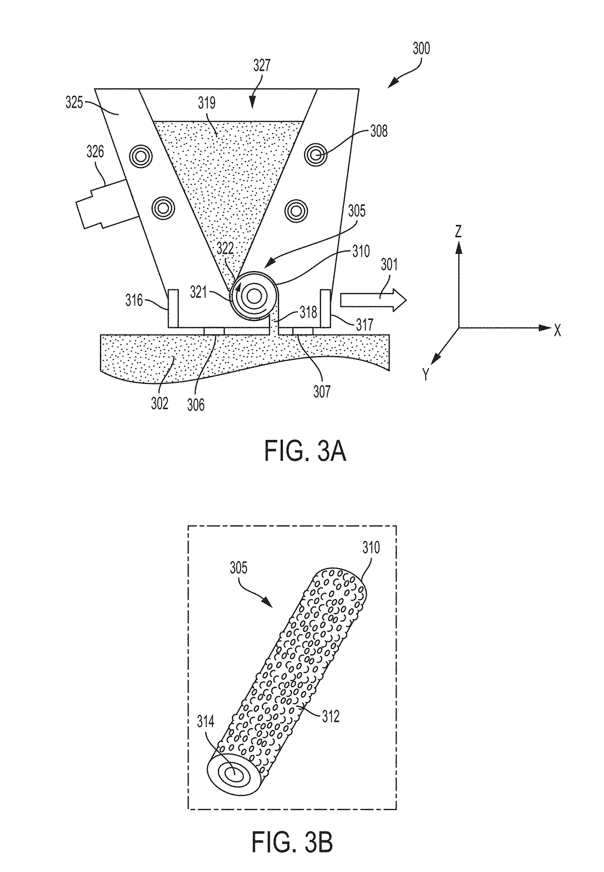
[0031]In one aspect of the invention, as shown in FIG. 3A, a recoater apparatus 300 is mounted movably mounted to an AM apparatus. The recoater apparatus 300 includes a powder hopper 325 for holding a powder 319 for use in an AM process. The recoater apparatus may be mounted to a track system, and / or rail system, and / or a robotic arm such that the movement of the recoater apparatus 300 can be controlled along the x-axis, y-axis, and / or the z-axis, for example. As shown in FIG. 3A, the recoater apparatus may extend along the y axis and may move across a powder bed 302 in a direction 301 which may be perpendicular to the x-axis. The powder bed 302 may include powder and / or an at least partially fused and / or sintered component being b...


PUM

PropertyMeasurementUnit
Lengthaaaaaaaaaa
Heightaaaaaaaaaa
Heightaaaaaaaaaa

Abstract

The present disclosure relates to systems, methods, and apparatuses for supplying powder to a powder bed during an additive manufacturing process. A recoater apparatus includes a powder reservoir and a powder distribution system for conveying powder from the powder reservoir to the powder bed. The recoater apparatus further includes at least two sweep strips, wherein at least one exit of the powder distribution system is located between the two sweep strips so as to shield the exit of the powder distribution system.

Description

INTRODUCTION[0001]The present disclosure generally relates to methods and systems adapted to perform additive manufacturing (“AM”) processes, for example by direct melt laser manufacturing (“DMLM”). The process utilizes an energy source that emits an energy beam to fuse successive layers of powder material to form a desired object. More particularly, the disclosure relates to methods and systems that utilize a recoater blades to distribute and smooth out the powder.BACKGROUND[0002]Additive manufacturing (AM) techniques may include electron beam freeform fabrication, laser metal deposition (LMD), laser wire metal deposition (LMD-w), gas metal arc-welding, laser engineered net shaping (LENS), laser sintering (SLS), direct metal laser sintering (DMLS), electron beam melting (EBM), powder-fed directed-energy deposition (DED), and three dimensional printing (3DP), as examples. AM processes generally involve the buildup of one or more materials to make a net or near net shape (NNS) object...

Claims


Application Information

Patent Timeline
IPC IPC(8): B22F3/105
CPCB22F3/1055B05D1/12B22F2003/1056B33Y40/00B29C31/02B33Y10/00B33Y30/00B22F2999/00B22F3/105B22F12/13B22F12/70B22F10/37B22F12/57B22F10/28B22F12/52B22F12/222B22F12/90B22F10/34B22F12/67B33Y40/10B29C64/218B29C64/205B29C64/343Y02P10/25
Inventor KELKAR, RAJENDRABARNHART, DAVID
Owner GENERAL ELECTRIC CO
Why Eureka
Try Eureka