Laser brazing of metal workpieces with relative movement between laser beam and filler wire

a metal workpiece and laser beam technology, applied in the direction of manufacturing tools, solvents, transportation and packaging, etc., can solve the problems of high-pressure zinc released into and around the molten filler material, adversely affecting the mechanical properties of the braze joint, and affecting the effect of laser beam focal distan

Inactive Publication Date: 2019-02-28
GM GLOBAL TECH OPERATIONS LLC
View PDF8 Cites 11 Cited by
  • Summary
  • Abstract
  • Description
  • Claims
  • Application Information

AI Technical Summary

Benefits of technology

[0014]A method of laser brazing a metal workpiece assembly according to yet version of the present disclosure may include several steps. In one step, a laser beam may be advanced along a joint seam established between a first metal workpiece and a second metal workpiece of a metal workpiece assembly. The laser beam has a focal point. In another step, a filler wire is fed into the laser beam as the laser beam is being advanced along the joint seam to melt a leading end of the filler wire, which is impinged by the laser beam, to produce and dispense molten filler material within and along the joint seam. This molten filler material solidifies behind the laser beam into a braze joint that metallurgically bonds the first and ...

Problems solved by technology

The aesthetic appearance of any joints formed on Class A surfaces are often demanding and subject to strict optical requirements to facilitate the look of a smooth singular surface when painted.
In certain situations—particularly when the metal workpieces are steel workpieces or aluminum alloy workpieces—laser brazing can be susceptible to joining discrepancies that may adversely affect the mechanical properties of the braze joint, the aesthetic appearance of the braze joint, most notably at its top surface, or both.
For example, when laser brazing together two steel workpieces coated with a zinc-based surface coating, such as zinc or a zinc-alloy, the heat associated with the laser brazing process may cause the zinc-based surface coating to boil in the vicinity of the joint seam, which can release high-pressure zinc into a...

Method used


Image

  • Laser brazing of metal workpieces with relative movement between laser beam and filler wire
  • Laser brazing of metal workpieces with relative movement between laser beam and filler wire
  • Laser brazing of metal workpieces with relative movement between laser beam and filler wire

Examples


Embodiment Construction

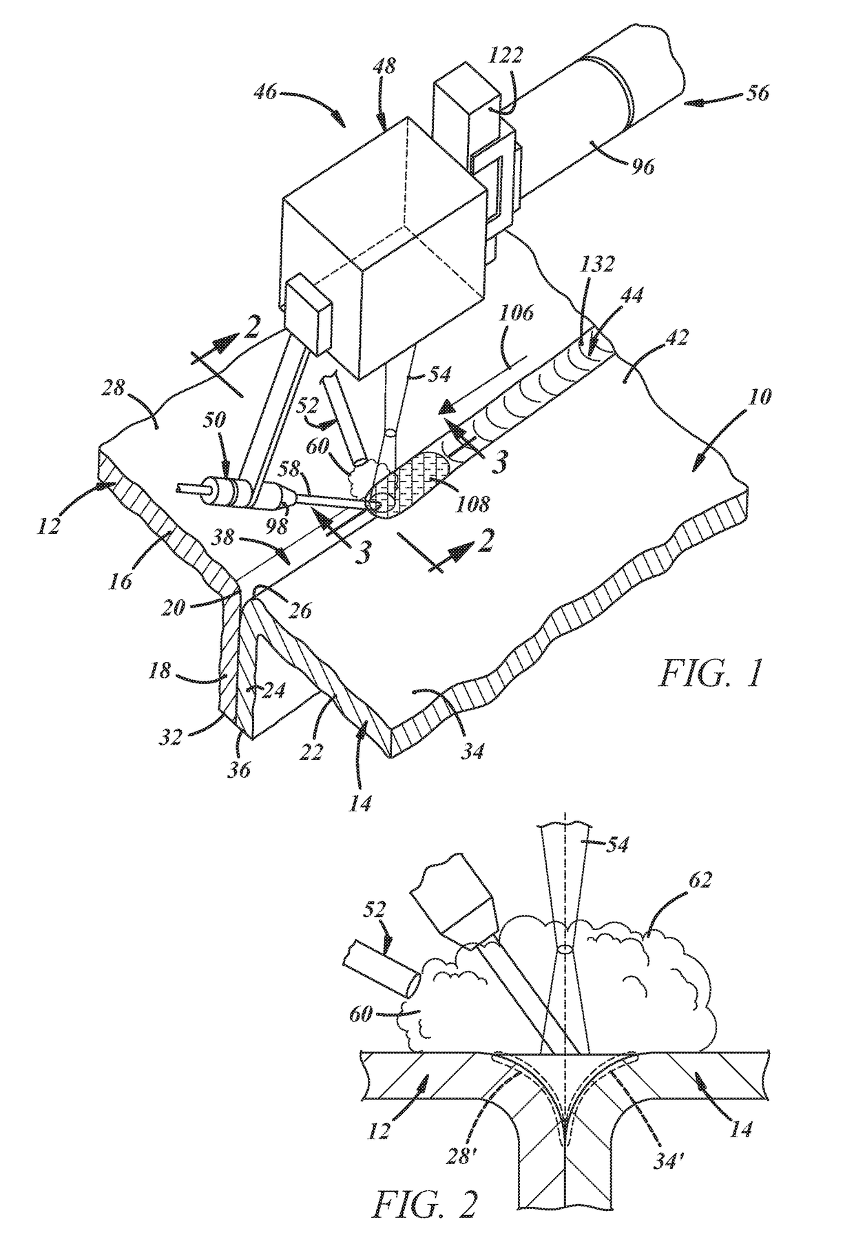
[0022]A method of laser brazing two metal workpieces together along a joint seam established between abutting metal workpieces is disclosed. The method involves engendering relative movement between an advancing laser beam and filler wire that is continuously fed into the laser beam along a forward feeding direction to dispense molten filler material along the joint seam. In particular, the aforementioned relative movement between the laser beam and the filler wire may be implemented by repeatedly fluctuating the position of a focal point of the laser beam relative to a leading end of the filler wire. Such repeated fluctuation can be achieved by executing one or more of the following actions: (1) oscillating the focal point of the laser beam along a longitudinal beam axis with respect to the metal workpiece assembly; (2) oscillating the filler wire along a direction parallel to an axial feeding direction of the filler wire; or (3) oscillating the filler wire in a direction transvers...


PUM

PropertyMeasurementUnit
Lengthaaaaaaaaaa
Lengthaaaaaaaaaa
Lengthaaaaaaaaaa

Abstract

A method of laser brazing a metal workpiece assembly along a joint seam established between a first metal workpiece and a second metal workpiece involves advancing a laser beam along the joint seam while feeding a filler wire into the laser beam to melt a leading end of the filler wire, which is impinged by the laser beam, to produce and dispense molten filler material within and along the joint seam. The dispensed molten filler material solidifies behind the laser beam into a braze joint. Additionally, as part of the method, a position of a focal point of the laser beam relative to the leading end of the filler wire is repeatedly fluctuated during advancement of the laser beam along at least part of the joint seam.

Description

TECHNICAL FIELD[0001]The technical field of this disclosure relates generally to laser brazing of metal workpieces and, more specifically, to a method for laser brazing metal workpieces with relative movement between the operating laser beam and the filler wire to enhance the quality of resultant the braze joint.INTRODUCTION[0002]There are many instances in a manufacturing setting where two metal workpieces need to be joined along a shared interface. The automotive industry, for example, often needs to secure two prefabricated metal panels together when constructing certain vehicle component parts. Laser brazing is one widely-employed joining technique that is particularly suitable for joint seams that are located along a Class A surface of the part being fabricated. A Class A surface is typically a styled and non-planar show surface that is present on the visible exterior of an assembled vehicle or other finished product. Vehicle component parts that include joints seams that will ...

Claims


Application Information

Patent Timeline
IPC IPC(8): B23K26/08B23K26/244B23K26/10
CPCB23K26/0869B23K2103/10B23K26/10B23K26/244B23K1/0056B23K1/0008B23K1/19B23K26/046B23K26/0884B23K26/14B23K26/147B23K26/211B23K2101/006B23K2101/18B23K2101/34B23K2101/35B23K2103/04
Inventor YANG, DAVIDWOLSKER, JUSTINCARLSON, BLAIRTAO, WU
Owner GM GLOBAL TECH OPERATIONS LLC
Why Eureka
Try Eureka