Spindle apparatus for use on a numerically controlled machine tool

Inactive Publication Date: 2019-02-28
DECKEL MAHO PFRONTEN GMBH
View PDF9 Cites 3 Cited by
  • Summary
  • Abstract
  • Description
  • Claims
  • Application Information

AI Technical Summary

Benefits of technology

[0040]For effective fastening of the rod elements, it is advantageous if the said rod elements are secured in the earthed part of the working spindle against unwanted movement by means of a thread. As an alternative, however, a screw can also secure the respective rod element in the spindle ap

Problems solved by technology

The problem occurs here that the highly sensitive measuring devices, such as structure-borne sound sensors or vibration sensors, but also pressure sensors and acceleration sensors, had partially considerable deviations and/or fluctuations in their measured data.
The result of tests in respect of the said observations is that the measuring devices

Method used


Image

  • Spindle apparatus for use on a numerically controlled machine tool
  • Spindle apparatus for use on a numerically controlled machine tool

Examples


Embodiment Construction

[0045]In the following text, examples and exemplary embodiments of the present invention will be described in detail with reference to the appended figures. Here, identical or similar elements in the figures can be denoted by identical reference numerals, but sometimes also by different reference numerals.

[0046]It is to be emphasized that the present invention is not limited or restricted in any way to the exemplary embodiments which are described in the following text and their embodiment features, but rather also includes modifications of the exemplary embodiments, in particular those which are included within the scope of protection of the independent claims as a result of modifications of the features of the described examples and / or by way of combination of single or multiple features of the described examples.

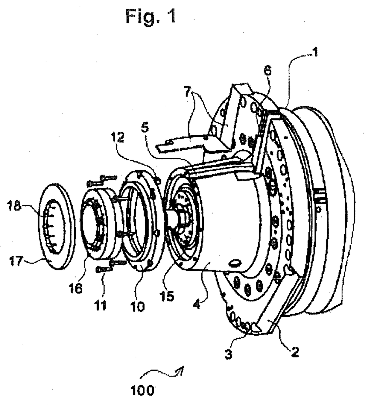
[0047]FIG. 1 shows an exemplary diagrammatic perspective exploded illustration of a spindle apparatus 100 for a numerically controlled machine tool (not shown), which spi...


PUM

PropertyMeasurementUnit
Angleaaaaaaaaaa
Angleaaaaaaaaaa
Forceaaaaaaaaaa

Abstract

The present invention relates to a spindle apparatus 100 for use on a numerically controlled machine tool, which spindle apparatus 100 has the following: a spindle housing 1, and a spindle shaft 15 which is mounted in the spindle housing, the spindle apparatus 100 having, furthermore, an electrically earthed section 4 which holds at least one rod element 20 which comprises an electrically conductive material, and the at least one rod element 20 being arranged in such a way that it makes contact with the spindle shaft 15 so as to bear tangentially against an outer circumference of the spindle shaft 15.

Description

[0001]The present invention relates to a spindle apparatus for use on a numerically controlled machine tool.BACKGROUND OF THE INVENTION[0002]Machine tools such as milling machines, lathes or grinding machines are currently state of the art in the field of the precise production of workpieces. Here, precision and reproducibility has been improved continuously in the past years in the case of machine tools; firstly by way of drives which can be actuated very precisely, but also by way of very accurate measuring systems which monitor the production process using a very wide variety of parameters and thus constantly give feedback to the controller about the actual state of the machining operation.[0003]DE 10 2013 201 328 A1 has disclosed a machining unit for a machine tool, which machining unit detects the movement of the spindle axis by means of an axially measuring sensor and a radially measuring sensor, which movement can occur on account of chips which adhere at the cut surface or o...

Claims


Application Information

Patent Timeline
IPC IPC(8): B23Q17/00B23Q17/09B23Q3/12B23Q15/14
CPCB23Q17/005B23Q17/0966B23Q3/12B23Q15/14B23Q17/2216B23Q1/70B23Q11/00B23Q17/00B23B2270/48B23Q5/04B23Q5/54B23Q17/12B23Q2717/00
Inventor JUNG, ROBERTVEITTINGER, HANS
Owner DECKEL MAHO PFRONTEN GMBH
Why Eureka
Try Eureka