Heat dissipation sheet and method for manufacturing heat dissipation sheet

a heat dissipation sheet and heat dissipation sheet technology, which is applied in the direction of lighting, heating apparatus, and semiconductor/solid-state device details, etc., can solve the problems of sacrificing the flexibility affecting the efficiency of the heat dissipation sheet, etc., to achieve high thermal conductive properties, the effect of sufficient flexibility

Inactive Publication Date: 2019-02-28
TOYOTA JIDOSHA KK
View PDF7 Cites 1 Cited by
  • Summary
  • Abstract
  • Description
  • Claims
  • Application Information

AI Technical Summary

Benefits of technology

[0010]The heat dissipation device described in JP 2006-253601 A has a configuration in which the tubular rhombic fins are provided in the rectangular support frame and has an advantage in which a number of thermally conductive paths with an equal length are formed between a top plate and a bottom plate that are heat dissipation surfaces or heat re

Problems solved by technology

Electronic components that generate heat on their own, such as a central processing unit (CPU), are likely to operate improperly when the temperature increases excessively.
What has been described above means a decrease in the ratio of the resin material, which, inevitably, sacrifices the flexibility of the heat dissipa

Method used


Image

  • Heat dissipation sheet and method for manufacturing heat dissipation sheet
  • Heat dissipation sheet and method for manufacturing heat dissipation sheet
  • Heat dissipation sheet and method for manufacturing heat dissipation sheet

Examples


second embodiment-1

[0075]FIG. 10 illustrates a second embodiment of the heat dissipation sheet. A heat dissipation sheet 200a of the second embodiment is different from the heat dissipation sheet 200 in terms of insulating layers 101 that are provided on the front and rear surfaces of the heat dissipation member 100 (100a). The rest of the configuration is the same as that of the heat dissipation sheet 200. As a material of the insulating layer 101, it is possible to use a material such as a thermosetting resin such as a silicone resin, an epoxy resin, or a urethane resin, a resin material such as a polyamide resin, a polyphenylene sulfide resin, or a polyimide resin, or a ceramic material such as alumina, silica, or boron nitride. When the insulating layers 101 are provided, the heat dissipation sheet 200a maintaining both a higher thermal conductivity and a higher insulating property can be obtained.

third embodiment

[0076]FIG. 11 illustrates a third embodiment of the heat dissipation sheet. In a heat dissipation sheet 200b of the third embodiment, the heat dissipation member 100 (100a) is formed using a material having insulating films 102 on the front and rear surfaces as the raw sheet 50 (50a). As a material of the insulating film 102, it is possible to use a material such as a thermosetting resin such as a silicone resin, an epoxy resin, or a urethane resin, a resin material such as a polyamide resin, a polyphenylene sulfide resin, or a polyimide resin, or a ceramic material such as alumina, silica, or boron nitride. In the heat dissipation sheet 200b as well, the heat dissipation member 100 has insulating performance, and thus it is possible to maintain both a higher thermal conductivity and a higher insulating property.

fourth embodiment

[0077]FIG. 12 illustrates a fourth embodiment of the heat dissipation sheet. In a heat dissipation sheet 200c of the fourth embodiment, as a heat dissipation member 100c, a heat dissipation member obtained by forming multiple stages of bent portions 103 in portions that extend in the thickness direction of the heat dissipation sheet 200c (the portions present between the mountain fold line p and the valley fold line q in the raw sheet 50 (50a)) is used. In the above-described configuration, the heat dissipation sheet 200c having an improved compression characteristic in the thickness direction can be obtained.

[0078]Hereinafter, the superiority of the heat dissipation sheet 200 according to the present disclosure will be described using examples and comparative examples.


PUM

PropertyMeasurementUnit
Thermal conductivityaaaaaaaaaa
Temperatureaaaaaaaaaa
Fractionaaaaaaaaaa

Abstract

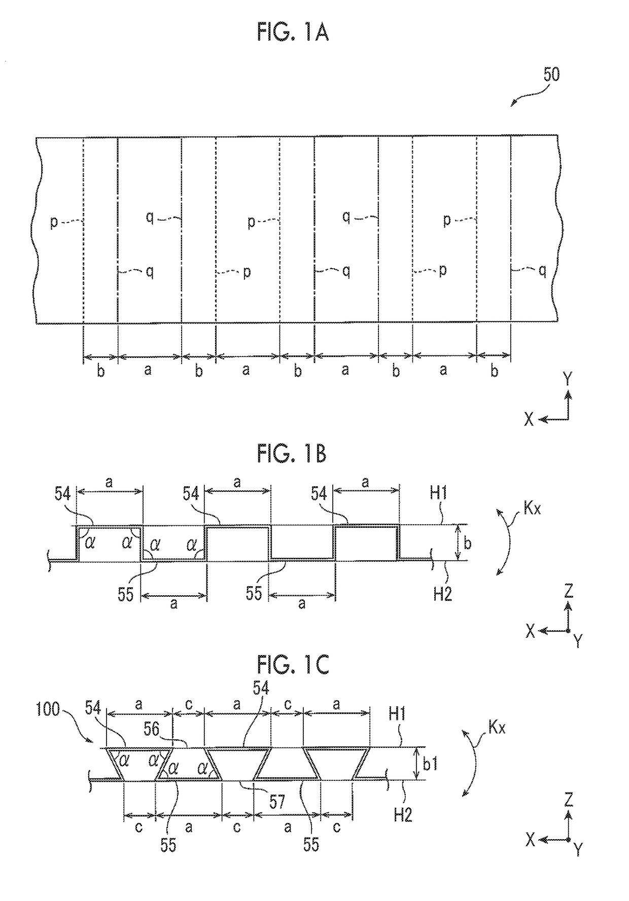
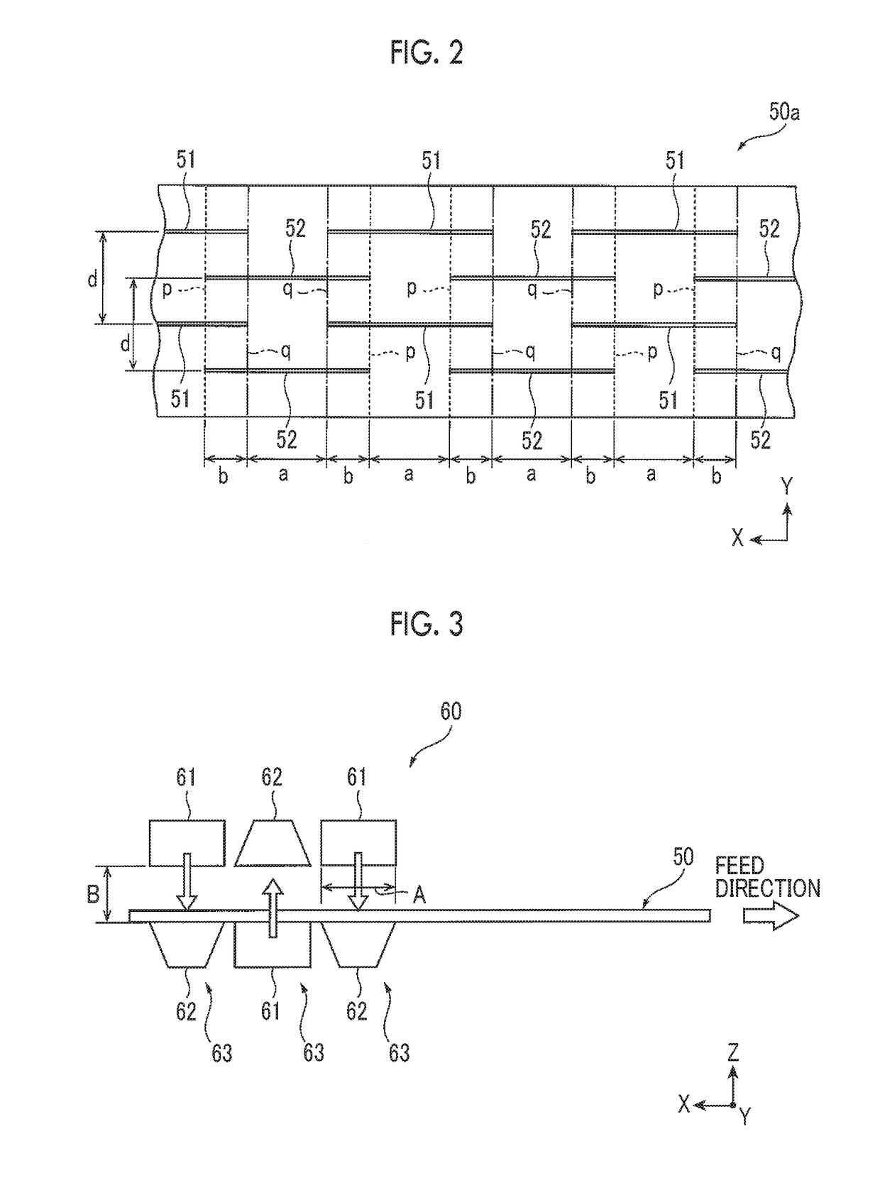
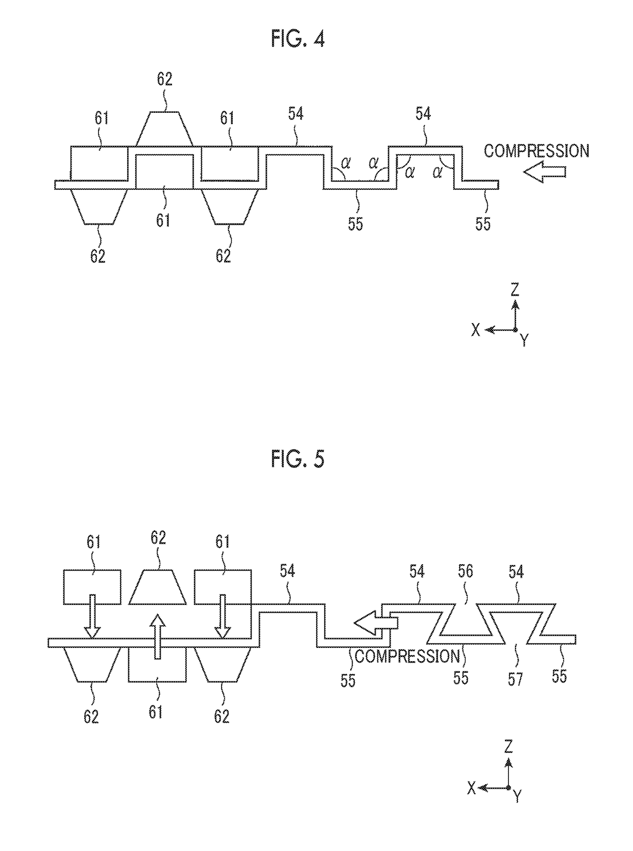
A heat dissipation sheet includes a resin material and a heat dissipation member that is made of a material with a higher thermal conductivity than the resin material. The heat dissipation member has protrusion bands and recess bands that are alternately arranged in parallel with one another. Top surfaces of the protrusion bands are flush with each other, and are located in a first horizontal surface. Bottom surfaces of the recess bands are flush with each other, and are located in a second horizontal surface. A first slit is provided between the top surfaces of the adjacent protrusion bands. A second slit is parallel to the first slit is provided between the bottom surfaces of the adjacent recess bands. Portions of the heat dissipation member other than both the top surfaces of the protrusion bands and the bottom surfaces of the recess bands are buried in the resin material.

Description

INCORPORATION BY REFERENCE[0001]The disclosure of Japanese Patent Application No. 2017-165421 filed on Aug. 30, 2017 including the specification, drawings and abstract is incorporated herein by reference in its entirety.BACKGROUND1. Technical Field[0002]The disclosure relates to a heat dissipation sheet that is suitable for dissipating heat generated from, for example, an electronic component generating heat to the outside and a method for manufacturing a heat dissipation sheet.2. Description of Related Art[0003]Electronic components that generate heat on their own, such as a central processing unit (CPU), are likely to operate improperly when the temperature increases excessively. In order to avoid such improper operation, an appropriate cooling device is used together with an electronic component. Examples of the cooling device as described above include the heat dissipation sheet described in Japanese Unexamined Patent Application Publication No. 2001-291810 (JP 2001-291810 A), t...

Claims


Application Information

Patent Timeline
IPC IPC(8): F28F21/06
CPCF28F21/067F28F2255/02F28F2270/00G06F1/20H01L21/4882H01L23/3672H01L23/3735H01L23/3736H01L23/3737F28F3/027F28F2013/005F28F2255/06F28F2255/146H01L21/4878H01L23/3733
Inventor YOSHIDA, YUJI
Owner TOYOTA JIDOSHA KK
Why Eureka
Try Eureka