Optical module and electronic apparatus

a technology of optical modules and electronic devices, applied in the direction of optical radiation measurement, instruments, spectrometry/spectrophotometry/monochromators, etc., can solve the problem that the light amount cannot be detected with high accuracy, and achieve the effect of improving the optical accuracy and improving the accuracy of various kinds of processing

Active Publication Date: 2019-02-28
SEIKO EPSON CORP
View PDF2 Cites 3 Cited by
  • Summary
  • Abstract
  • Description
  • Claims
  • Application Information

AI Technical Summary

Benefits of technology

[0024]According to the above optical module, since it is possible to improve the optical accuracy, it is possible to improve accuracy of various kinds of processing using the optical module in an electronic device including the optical module.

Problems solved by technology

In this case, there is a problem that not only light passing through the wavelength tunable interference filter but also light (stray light) passing through the inside of the circuit substrate and emitted into the concave portion is also received by the optical sensor, and the light amount of light may not be detected with high accuracy.

Method used


Image

  • Optical module and electronic apparatus
  • Optical module and electronic apparatus
  • Optical module and electronic apparatus

Examples


first embodiment

[0033]Hereinafter, a first embodiment of the invention will be described with reference to drawings. In the present embodiment, a spectroscopic measurement apparatus 1 as an electronic apparatus including an optical module 10 will be described.

Structure of Spectroscopic Measurement Apparatus

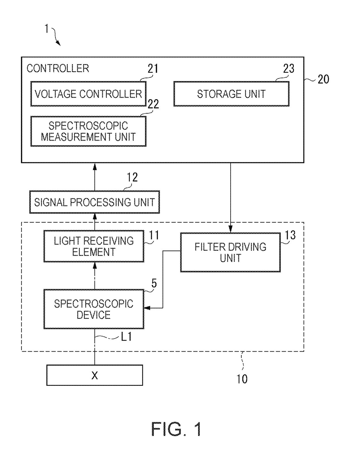
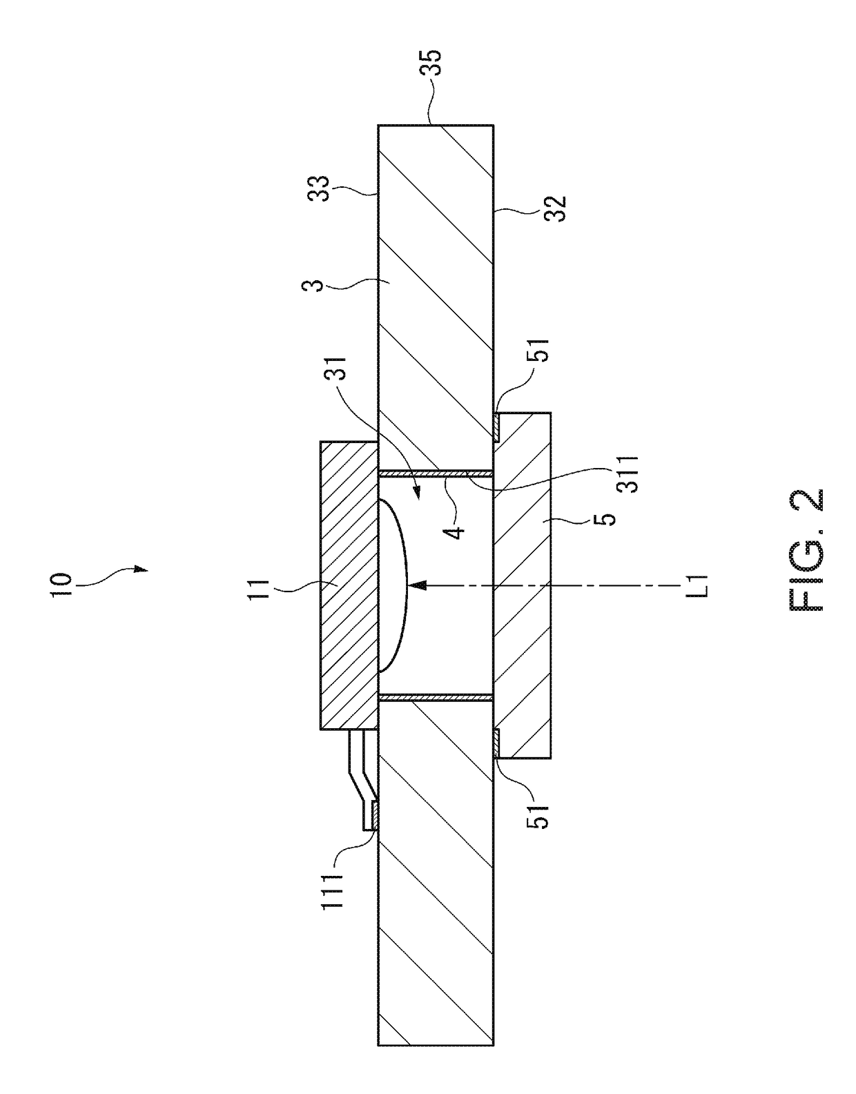
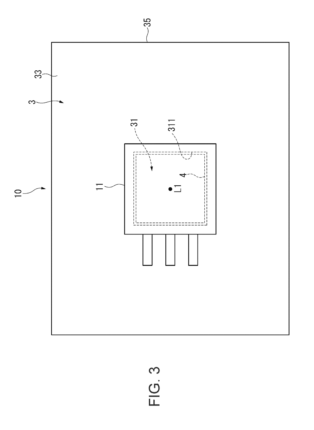
[0034]As shown in FIG. 1, the spectroscopic measurement apparatus 1 is configured to include a spectroscopic device 5 and measures a light amount of light of each wavelength in measurement target light reflected by or emitted from a measurement target object X. Specifically, the spectroscopic measurement apparatus 1 includes the optical module 10 including the spectroscopic device 5, a light receiving element 11, and a filter driving unit 13, and a signal processing unit 12 and a controller 20.

[0035]The spectroscopic device 5 is configured to include, for example, a spectroscopic element capable of changing a spectral wavelength when light from the measurement target object X is dispersed. In the...

second embodiment

[0055]In an optical module 10A of a second embodiment, the first light shielding portion 4 is not provided on the inner peripheral surface 311 of the first hole portion 31. Instead, in the wiring board 3 in the substrate plan view, a second light shielding portion 34 is provided on the outer peripheral side of the wiring substrate 3 with respect to the first hole portion 31. Other configurations are the same as those of the optical module 10 of the first embodiment. The same components as those of the optical module 10 are denoted by the same reference numerals, and description thereof is omitted.

[0056]FIG. 4 is a cross-sectional view of the optical module 10A, and FIG. 5 is a plan view of the optical module 10A.

[0057]As shown in FIGS. 4 and 5, the wiring substrate 3 of the optical module 10A includes the second light shielding portion 34 that surrounds the periphery of the first hole portion 31 on the outer peripheral side of the wiring substrate 3 with respect to the first hole po...


PUM


Abstract

An optical module includes a substrate that has a first surface and a second surface opposite to the first surface and provided with a first hole portion having an opening surface on at least the first surface, an optical element that is provided on the substrate, the optical element having an optical axis located along a thickness direction from the first surface toward the second surface and located in the first hole portion, and a first light shielding portion that is provided on an inner peripheral surface which intersects the opening surface of the first hole portion and has a higher light shielding property than the substrate.

Description

BACKGROUND1. Technical Field[0001]The present invention relates to an optical module and an electronic apparatus.2. Related Art[0002]In the related art, there is known an optical module in which an optical element such as a light receiving element is provided on a circuit substrate (for example, JP-A-2015-161511).[0003]In the optical module of JP-A-2015-161511, a wavelength tunable interference filter is provided on one side of the circuit substrate. Furthermore, a concave portion is provided on one surface side of the circuit substrate, and an optical sensor (light receiving element) for receiving the light transmitted through the wavelength tunable interference filter is provided in the concave portion.[0004]Meanwhile, in the optical module as disclosed in JP-A-2015-161511, a glass epoxy substrate in which glass fibers are impregnated with epoxy resin or the like is sometimes used as a circuit substrate. Such a glass epoxy substrate has light-transmittance. Normally, a resist is f...

Claims


Application Information

Patent Timeline
Patent Type & Authority Applications(United States)
IPC IPC(8): G01J1/04G02B7/00
CPCG01J1/0437G01J1/0488G01J1/44G02B6/12G02B7/00G01J1/0204G01J3/0256G01J3/32G01J3/0262G01J1/0214
Inventor ASAUCHI, NOBORU
Owner SEIKO EPSON CORP
Why Eureka
Try Eureka