Ultrasonic apparatus

a technology of ultrasonic apparatus and output signal, which is applied in the field of ultrasonic apparatus, can solve the problems of small signal-to-noise ratio (snr) of output signal of the probe, and decrease in measurement accuracy, so as to reduce the influence of electromagnetic waves and achieve high-quality subject information.

Inactive Publication Date: 2019-02-28
CANON KK
View PDF0 Cites 2 Cited by
  • Summary
  • Abstract
  • Description
  • Claims
  • Application Information

AI Technical Summary

Benefits of technology

[0006]In view of the above discussion, the present disclosure is directed to providing an ultrasonic apparatus capable of reducing the influence of an electromagnetic wave generated from an electronic device provided outside a transmission unit and acquiring highly accurate subject information.

Problems solved by technology

A signal transmitted from the transmission unit, however, includes noise under the influence of an electromagnetic wave generated from an electronic device provided outside the transmission unit.
As a result, the signal-to-noise ratio (SNR) of an output signal from the probe becomes small, and the measurement accuracy decreases.

Method used


Image

  • Ultrasonic apparatus
  • Ultrasonic apparatus
  • Ultrasonic apparatus

Examples


Embodiment Construction

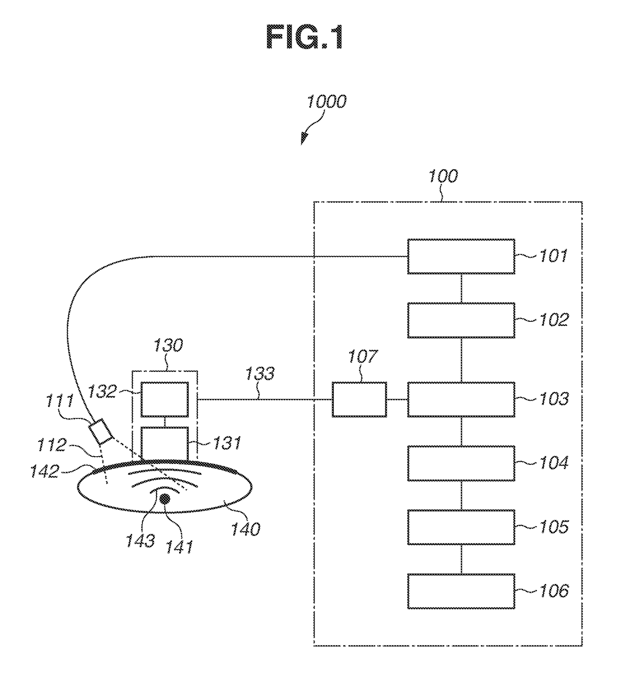
[0015]With reference to FIG. 1, an ultrasonic apparatus according to exemplary embodiments of the present invention is described.

[0016]An ultrasonic apparatus 1000 according to the present exemplary embodiments includes an ultrasonic reception unit 131, which receives an ultrasonic wave 143 generated from a subject 140 and outputs a reception signal, an amplifier 132, which amplifies the intensity of the reception signal, and a transmission unit 133, which transmits an amplification signal obtained by amplifying the reception signal. Further, the ultrasonic apparatus 1000 includes an attenuator 107, which outputs an attenuation signal obtained by attenuating the intensity of the transmitted amplification signal, and an acquisition unit 103, which acquires information regarding the subject 140 at least based on the output attenuation signal.

[0017]In the ultrasonic apparatus 1000 according to the present exemplary embodiments, the amplifier 132 amplifies the reception signal, and then...


PUM


Abstract

An ultrasonic apparatus includes an ultrasonic reception unit configured to receive an ultrasonic wave generated from a subject and output a reception signal, an amplifier configured to amplify an intensity of the reception signal, a transmission unit configured to transmit an amplification signal obtained by amplifying the reception signal, an attenuator configured to output an attenuation signal obtained by attenuating an intensity of the transmitted amplification signal, and an acquisition unit configured to acquire information regarding the subject at least based on the attenuation signal.

Description

BACKGROUNDField of the Disclosure[0001]The present disclosure relates to an ultrasonic apparatus.Description of the Related Art[0002]An optical imaging apparatus for irradiating a living body with light from a light source such as a laser and generating an image of information about the inside of the living body obtained based on the irradiation light is actively studied in the medical field.[0003]As one of optical imaging techniques, there is photoacoustic tomography (PAT). In PAT, a living body is irradiated with pulsed light generated from a light source, and an acoustic wave generated from living tissue absorbing the energy of the pulsed light propagated and diffused in the living body is detected. That is, using the difference in the absorption rate of light energy between a subject part such as tumor and tissue other than the subject part, a reception element receives an elastic wave, i.e., a photoacoustic wave, which is generated when the subject part instantaneously expands ...

Claims


Application Information

Patent Timeline
Patent Type & Authority Applications(United States)
IPC IPC(8): G01S15/89G01S7/52
CPCG01S15/8965G01S7/52085G01S7/52077G01S7/52025A61B5/0095A61B5/72G01S15/899A61B5/7217
Inventor SUWA, TAKESHI
Owner CANON KK
Why Eureka
Try Eureka