Organic electroluminescence device, method for producing organic electroluminescence device, illumination device, and display device
- Summary
- Abstract
- Description
- Claims
- Application Information
AI Technical Summary
Benefits of technology
Problems solved by technology
Method used
Image
Examples
first embodiment
[0054]An organic EL device of a first embodiment will be described hereinafter.
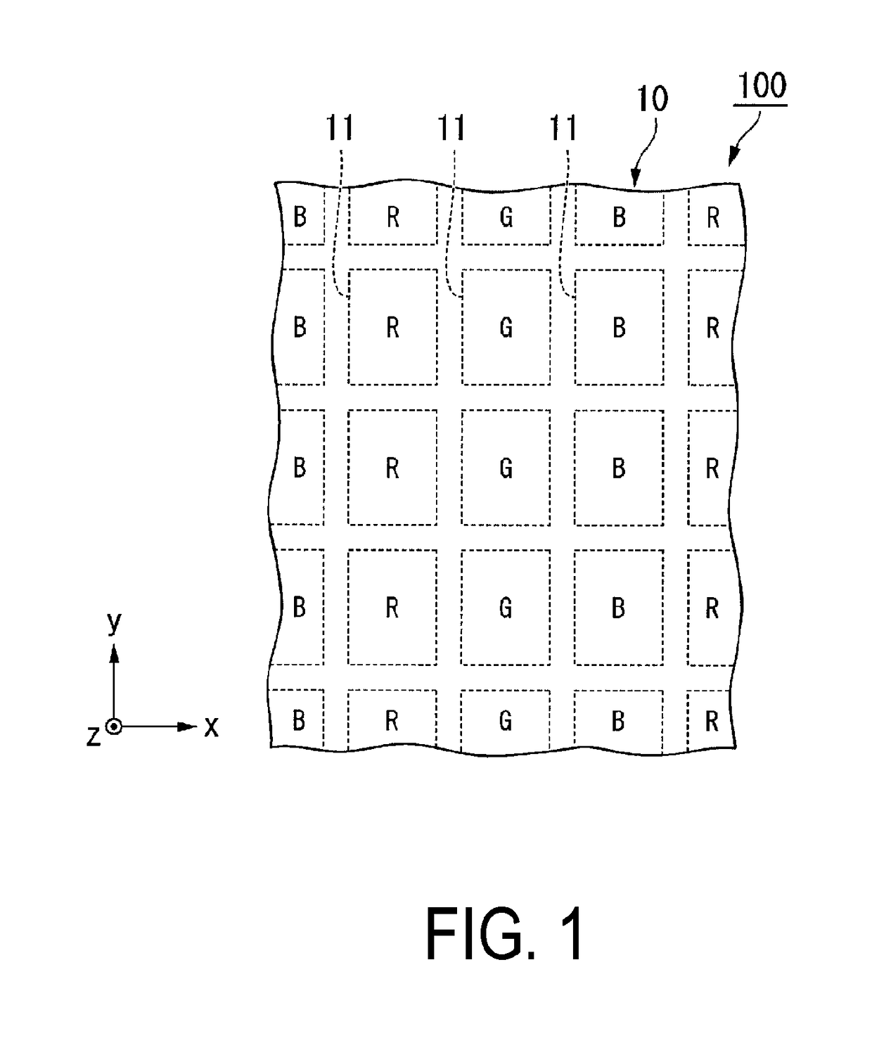
[0055]FIG. 1 is a drawing illustrating a display region of an organic EL device of the first embodiment.
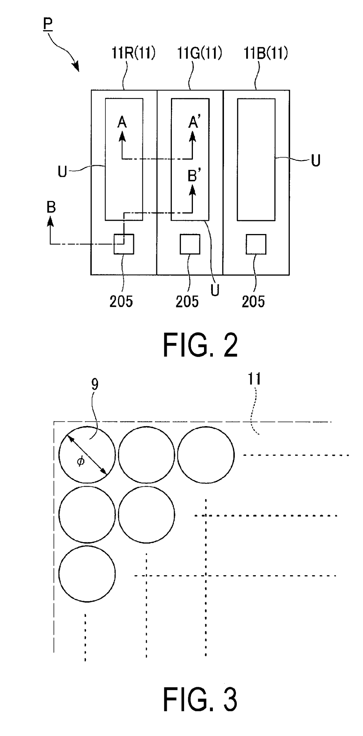
[0056]FIG. 2 is a plan view illustrating one pixel in the organic EL device of the first embodiment.
[0057]FIG. 3 is a magnified plan view illustrating a portion of the sub-pixel in FIG. 2.
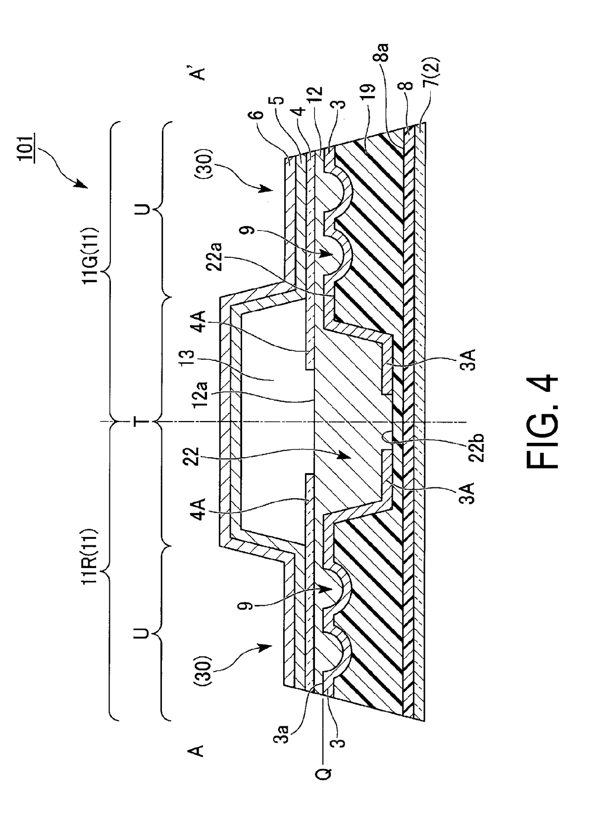
[0058]FIG. 4 is a drawing illustrating the configuration between sub-pixels and is a cross-sectional view along line A-A′ in FIG. 2.
[0059]As illustrated in FIG. 1, the organic EL device (organic electroluminescence device, illumination device, and display device) 100 of this embodiment includes a plurality of unit light emitting regions 11 separated from one another. Here, the organic EL device includes a display region 10 including a plurality of unit light emitting regions 11 corresponding to RGB. Each unit light emitting region 11 extends in a striped shape along the y-axis and is arranged repeatedly in the order of...
second embodiment
[0144]Next, an organic EL device of a second embodiment of the disclosure will be described.
[0145]The basic structure of the organic EL device of this embodiment described below is substantially the same as that of the first embodiment described above, but differs in the configuration of the organic EL element. Therefore, in the following description, the portions different from the previous embodiment will be described in detail, and the description of parts in common will be omitted. In addition, in each of the drawings used in the description, components that are common to FIGS. 1 to 5 are labeled with the same symbols.
[0146]FIG. 9 is a cross-sectional view partially illustrating a structure between sub-pixels in the organic EL device of a second embodiment. FIG. 10 is a cross-sectional view partially illustrating a structure between sub-pixels in the organic EL device of the second embodiment. FIG. 11 is a partially magnified partial cross-sectional view illustrating an excavate...
third embodiment
[0167]Next, an organic EL device of a third embodiment of the disclosure will be described.
[0168]The basic structure of the organic EL device of this embodiment described below is substantially the same as that of the first embodiment described above, but differs with regard to the excavated structure. Therefore, in the following description, the portions different from the previous embodiment will be described in detail, and the description of parts in common will be omitted. In addition, in each of the drawings used in the description, components that are common to FIGS. 1 to 5A are labeled with the same symbols.
[0169]FIG. 14 is a cross-sectional view partially illustrating a structure between sub-pixels in the organic EL device of a third embodiment. FIGS. 15A and 15B are drawings for describing the production method of the excavated structure.
[0170]In the organic EL device of this embodiment, as illustrated in FIG. 14, a reflective layer 3, a first electrode 4 (end portion 4A), ...
PUM
 Abstract
Description
Claims
Application Information
 - R&D
- Intellectual Property
- Life Sciences
- Materials
- Tech Scout
- Unparalleled Data Quality
- Higher Quality Content
- 60% Fewer Hallucinations
Browse by: Latest US Patents, China's latest patents, Technical Efficacy Thesaurus, Application Domain, Technology Topic, Popular Technical Reports.
© 2025 PatSnap. All rights reserved.Legal|Privacy policy|Modern Slavery Act Transparency Statement|Sitemap|About US| Contact US: help@patsnap.com


