A device and method for heating or cooling a sample

a sample and device technology, applied in the field of devices and/or methods for heating or cooling a sample, can solve the problems of reducing and affecting the heating effect or agitation. , to achieve the effect of decreasing and increasing the heating effect or agitation

Active Publication Date: 2019-03-14
CELL THERAPY CATAPULT
View PDF6 Cites 16 Cited by
  • Summary
  • Abstract
  • Description
  • Claims
  • Application Information

AI Technical Summary

Benefits of technology

[0116]The characteristic / s of the temperature control members, and / or the sample, and / or the container within which the sample is contained may be monitored using one or more sensors. The one or more sensors may comprise one or more temperature sensors and the method may comprise using the one or more temperature sensors to monitor the temperature of one or more of the members, and / or the sample, or at least one or more regions within the sample, and / or the temperature of the container within which the sample is contained, or at least one or more regions within the container. For example, in some embodiments the method may comprise using one or more temperature sensors to monitor the temperature of at least a portion of a wall of the container, which may be an interior or exterior wall. The method may comprise monitoring the temperature of both the sample and the container. In some embodiments the method may additionally comprise varying the heating profile and / or agitation provided by, for example, increasing the heating effect or agitation at areas which are determined to have a low temperature (with respect to the target temperature to which the sample is to be heated), or conversely decreasing the heating effect or agitation in areas which are determined to have a temperature closer to the target temperature to which the sample is to be heated, i.e. at those areas which have thawed quickest.
[0117]In further embodiments the method may comprise using one or more sensors to monitor structural characteristics of the sample. For example, in some embodiments the method may comprise using one or more structural sensors to determine the ice fraction of the sample. In embodiments wherein the method comprises heating / thawing a sample, the one or more structural sensors may be used to monitor the changes in the ice fraction of the sample as it thaws / heats. The method may further comprise varying the heating profile and / or agitation provided by, for example, increasing the heating effect or agitation at areas which have a high ice fraction, or conversely decreasing the heating effect or agitation at areas which have a low ice fraction, i.e. at those areas which have thawed quickest. For example, the agitation may be changed when a particular ice fraction is determined to be present in the sample, e.g. when the sample is less than 99, 95, 90, 85, 80, 75, 70, 65, 60, 55, 50, 45, 40, 35, 30, 25, 20, 15, 10 or 5% ice in volume, or particularly, wherein less than 99, 95, 90, 85, 80, 75, 70, 65, 60, 55, 50, 45, 40, 35, 30, 25, 20, 15, 10 or 5% of the water in the sample is ice.

Problems solved by technology

However, thawing samples in this manner raises issues in relation to the sterility of the water (or fluid) within which the bags / containers are submerged and sample contamination may therefore be an issue.
However, it is characteristically difficult in a dry system to apply sufficient power to thaw samples without exceeding the maximum temperature to which samples should be heated.
Furthermore, when freezing samples contained within a bag, the bag upon freezing, may flex.
Dry systems of the art comprising a planar heating element will not provide a uniform heating profile across the bag when flex has occurred during freezing.
However, as discussed, it is characteristically difficult to maintain a constant temperature profile across a sample using a dry system with planar heating / cooling elements, particularly when freezing samples within a flexible bag as the bag may flex during the process.

Method used


Image

  • A device and method for heating or cooling a sample
  • A device and method for heating or cooling a sample
  • A device and method for heating or cooling a sample

Examples


first embodiment

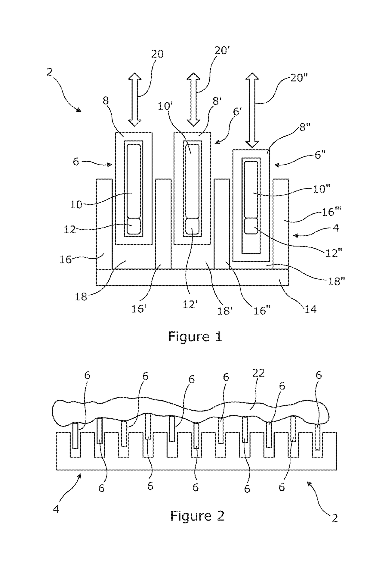
[0139]FIG. 1 is a side cross sectional view of a portion of a device in accordance with the invention;

[0140]FIG. 2 is a further side cross sectional view of the device of FIG. 1;

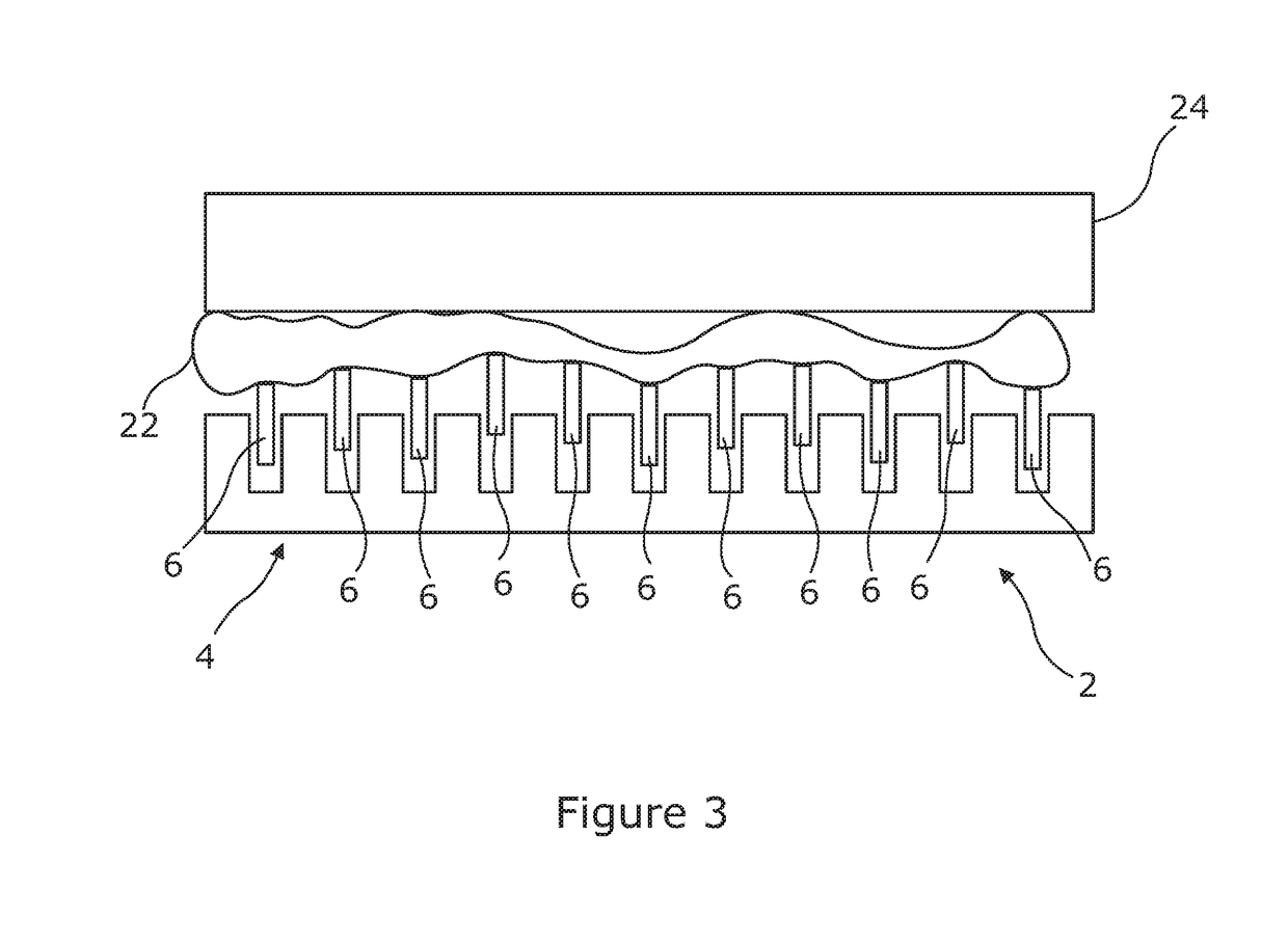
[0141]FIG. 3 is a side cross sectional view of a variant of the device shown in FIGS. 1 and 2;

second embodiment

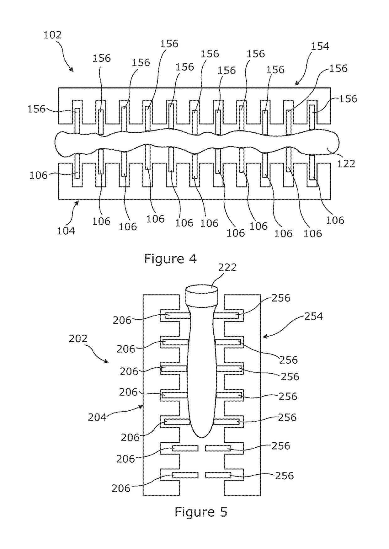
[0142]FIG. 4 is a side cross sectional view of a device in accordance with the invention;

third embodiment

[0143]FIG. 5 is a side cross sectional view of a device in accordance with the invention;

[0144]FIG. 6 is a perspective view of a further embodiment of a device of the present invention;

[0145]FIG. 7 is a further perspective view of a still further embodiment of a device in accordance with of the present invention;

[0146]FIG. 8 is a further perspective view of the device of FIG. 7;

[0147]FIG. 9 shows a prototype device of the invention comprising upper and lower temperature sensors and an EVA cover to protect the device from contamination;

[0148]FIGS. 10A-D are a series of perspective views of a device in accordance with a yet further embodiment of the invention in different stages of assembly and from different angles;

[0149]FIG. 11 is a perspective view of part of a further embodiment of a device in accordance an aspect of the invention;

[0150]FIG. 12 shows a force-limited oscillating agitator which can be incorporated into a device in accordance with the invention;

[0151]FIG. 13 is a gra...


PUM


Abstract

A sample heating/cooling device comprises a plurality of members operable in use to heat and/or cool one or more samples. Each member has a sample contact surface and is biased towards a resting position under the operation of a biasing means. The members are movable independently of one another against said bias under the application of a force on the sample contact surface and so are able to conform to the shape of a sample placed on the members to provide a uniform heating/cooling profile. The members may be mounted in a heating/cooling element and adapted to conduct thermal energy between the sample and the element. The device is particularly suitable for thawing frozen sample bags having an irregular shape. A corresponding method is also described.

Description

TECHNICAL FIELD OF THE INVENTION[0001]The present invention relates to improvements in or relating to devices and / or methods for heating or cooling a sample and in particular, in relation to devices and / or methods for heating, thawing, cooling and / or freezing samples enclosed within bags or other containers.BACKGROUND TO THE INVENTION[0002]Samples are routinely stored within bags or other containers and are often chilled or frozen to preserve or improve shelf-life. Such chilled or frozen samples often need to be thawed or heated before use wherein it is usually desirable to carry out any thawing or heating in a safe and efficient manner. Further, in certain instances the maximum temperature of the sample may need to be kept below a certain value during and / or after heating / thawing, for example, where the samples comprise biological material or food products; whilst simultaneously ensuring that the sample is not contaminated in any way. In an exemplary case, where the frozen sample c...

Claims


Application Information

Patent Timeline
Patent Type & Authority Applications(United States)
IPC IPC(8): A01N1/02A61M1/02B01J19/00B01L3/00B01L7/00B01L9/00F28D11/08F28F5/00
CPCA01N1/0257A61M1/0272B01J19/00B01L3/505B01L7/00B01L9/00F28D11/08F28F5/00B01J2219/00087B01J2219/00961B01L2300/0829B01L2300/1822B01L2300/1827B01L2300/185B01L2300/1894B01L3/00C12M41/22C12M27/16C12M45/20A01N1/0252B01J2219/00051B01L2300/1805B01L2200/147
Inventor MILNE, STUARTNANCEKIEVILL, ALEXCREASEY, CHRISTOPHERLAMB, STEPHENRUTLEDGE, RUPERT
Owner CELL THERAPY CATAPULT
Why Eureka
Try Eureka