Method and Apparatus to Diagnose a Linear Synchronous Motor System

a technology of linear drive and synchronous motor, which is applied in the direction of testing/monitoring control system, program control, instruments, etc., can solve the problems of inability to readily observe the failure of a coil in a linear drive system is difficult to detect the failure of components, and the failure of a coil in a linear drive system is difficult to d

Active Publication Date: 2019-03-14
ROCKWELL AUTOMATION
View PDF0 Cites 11 Cited by
  • Summary
  • Abstract
  • Description
  • Claims
  • Application Information

AI Technical Summary

Problems solved by technology

A linear drive system presents challenges for detecting component failures that are not seen in rotary motors or rotary drive systems.
Whereas failure of a coil in a stator of a rotary machine is readily observed due to repeated activation and subsequent degradation in performance, failure of a coil in a linear drive syste

Method used


Image

  • Method and Apparatus to Diagnose a Linear Synchronous Motor System
  • Method and Apparatus to Diagnose a Linear Synchronous Motor System
  • Method and Apparatus to Diagnose a Linear Synchronous Motor System

Examples


Embodiment Construction

[0024]The various features and advantageous details of the subject matter disclosed herein are explained more fully with reference to the non-limiting embodiments described in detail in the following description.

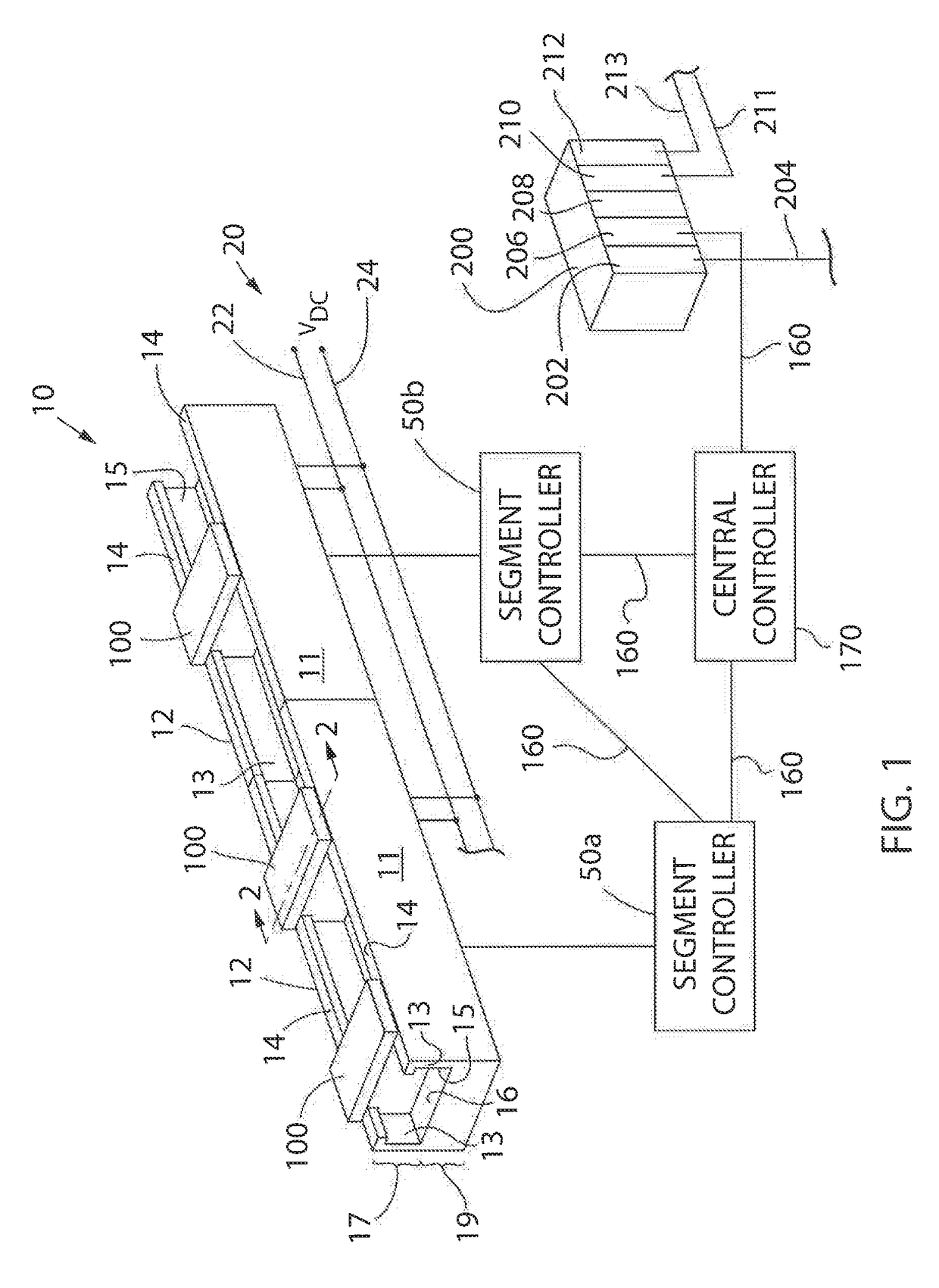
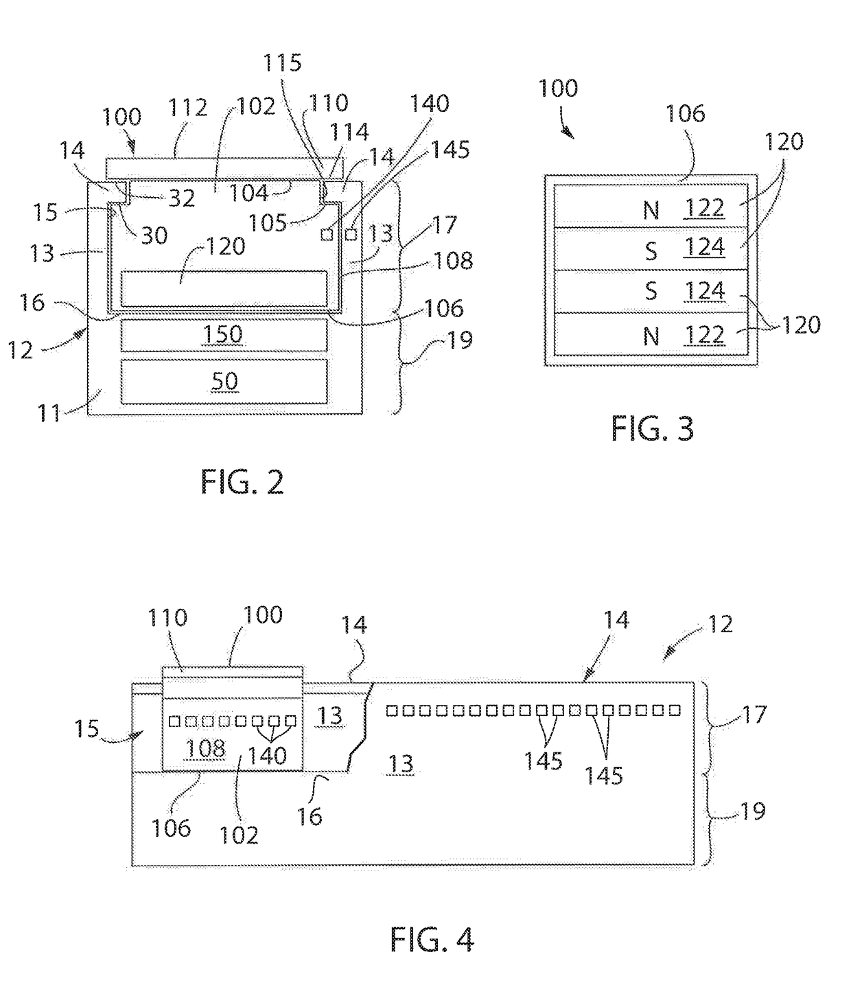
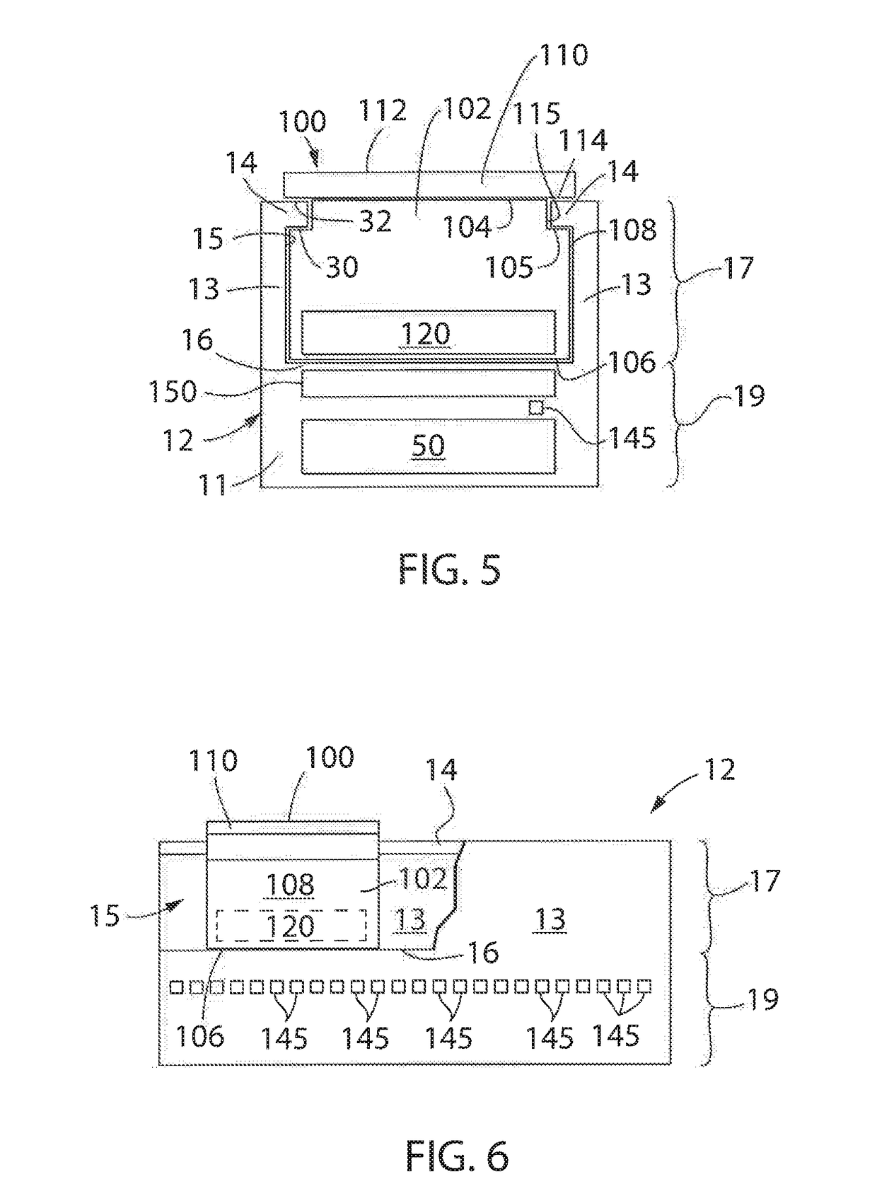
[0025]Turning initially to FIGS. 1-4, an exemplary transport system for moving articles or products includes a track 10 made up of multiple segments 12. According to the illustrated embodiment, multiple segments 12 are joined end-to-end to define the overall track configuration. The illustrated segments 12 are both straight segments having generally the same length. It is understood that track segments of various sizes, lengths, and shapes may be connected together to form the track 10 without deviating from the scope of the invention. Track segments 12 may be joined to form a generally closed loop supporting a set of movers 100 movable along the track 10. The track 10 is illustrated in a horizontal plane. For convenience, the horizontal orientation of the track 10 shown in ...


PUM


Abstract

A method and system for detecting and reporting component failures in a linear drive system may identify failed position sensors, failed position magnets, and failed drive coils in the linear drive system. As a mover travels along a track segment in the linear drive system, signals corresponding to the position of the mover and to the current commanded in each drive coil are stored. Analysis of the stored signals identifies whether one of the position sensors along the track segment, one of the position magnets on the movers, or one of the drive coils, used to propel the movers along the track, has failed.

Description

BACKGROUND INFORMATION[0001]The present invention relates to motion control systems and, more specifically, to diagnosing failure conditions in a linear drive system in a motion control system, where the motion control system incorporates multiple movers propelled along a track using the linear drive system.[0002]Motion control systems utilizing movers and linear motors can be used in a wide variety of processes (e.g. packaging, manufacturing, and machining) and can provide an advantage over conventional conveyor belt systems with enhanced flexibility, extremely high-speed movement, and mechanical simplicity. The motion control system includes a set of independently controlled “movers” each supported on a track for motion along the track. The track is made up of a number of track segments that, in turn, hold individually controllable electric coils. Successive activation of the coils establishes a moving electromagnetic field that interacts with the movers and causes the mover to tr...

Claims


Application Information

Patent Timeline
IPC IPC(8): B65G43/02B65G35/06B65G54/02G05B19/042B65G43/06B60L13/10H02P6/00B60L15/00
CPCH02P6/006G05B19/0421B65G43/02B60L13/10B65G54/02B60L15/005B65G43/06B65G35/06G05B23/0205G01R31/00G01R31/56
Inventor HUANG, YUHONG
Owner ROCKWELL AUTOMATION
Why Eureka
Try Eureka