Stray field rejection in magnetic sensors

a magnetic sensor and field sensor technology, applied in the direction of stray field compensation, electrical/magnetically converting sensor output, instruments, etc., can solve the problems of field sensors subject to measurement error, difficult or too expensive, and significant measurement errors still possibl

Active Publication Date: 2019-03-14
MELEXIS TECH NV
View PDF6 Cites 10 Cited by
  • Summary
  • Abstract
  • Description
  • Claims
  • Application Information

AI Technical Summary

Benefits of technology

[0020]Embodiments of the present invention provide a field sensor device with sensor field signals having improved accuracy and precision and improved stray field rejection.

Problems solved by technology

Nonetheless, significant measurement errors are still possible.
However, in other applications such calibration is not possible, difficult or too expensive.
Moreover, field sensors are subject to measurement error due to stray fields that are unrelated to the field whose measurement is desired.
However, this can require larger, heavier or bulkier magnets and / or more accurate mechanical assembly with more stringent tolerances, thereby increasing size and / or cost.

Method used


Image

  • Stray field rejection in magnetic sensors
  • Stray field rejection in magnetic sensors
  • Stray field rejection in magnetic sensors

Examples


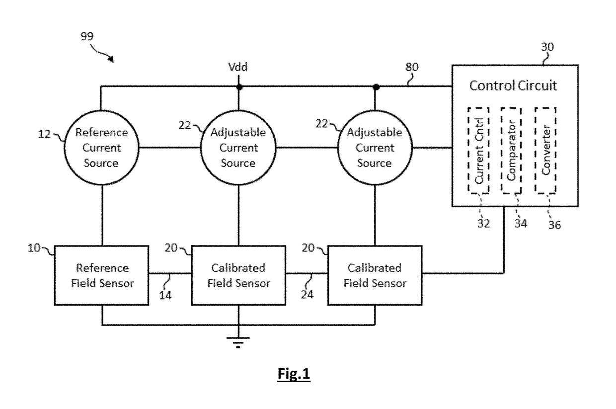
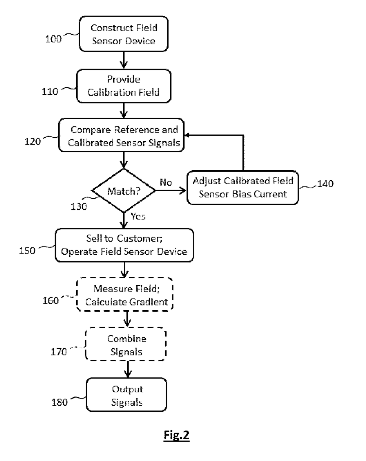
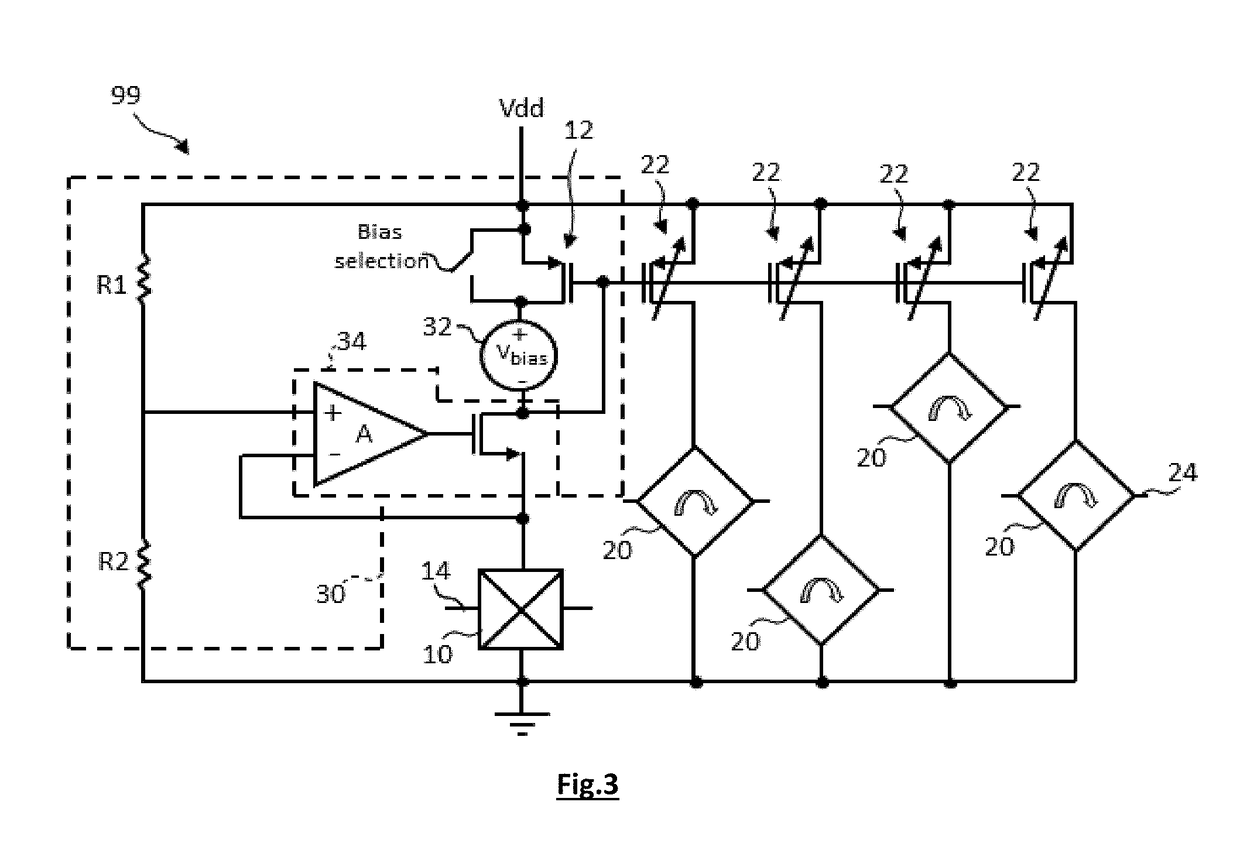
Embodiment Construction

[0029]The present invention will be described with respect to particular embodiments and with reference to certain drawings but the invention is not limited thereto but only by the claims.

[0030]Furthermore, the terms first, second and the like in the description and in the claims, are used for distinguishing between similar elements and not necessarily for describing a sequence, either temporally, spatially, in ranking or in any other manner. It is to be understood that the terms so used are interchangeable under appropriate circumstances and that the embodiments of the invention described herein are capable of operation in other sequences than described or illustrated herein.

[0031]It is to be noticed that the term “comprising”, used in the claims, should not be interpreted as being restricted to the means listed thereafter; it does not exclude other elements or steps. It is thus to be interpreted as specifying the presence of the stated features, integers, steps or components as re...


PUM


Abstract

A field-sensor device comprises a reference field sensor biased with a reference current. The reference field sensor provides a reference sensor signal in response to a field, and a calibrated field sensor biased with an individually adjustable current and providing a calibrated sensor signal in response to the field. A control circuit controls the adjustable current bias of the calibrated field sensor at a calibrated current different from the reference current so that the calibrated field sensor provides a calibrated sensor signal substantially equal to the reference sensor signal in response to a common field. The field sensor device is arranged to be exposed, when in a calibration mode, to a uniform calibration field and, when in operational mode, to an operational field being a field gradient.

Description

FIELD OF THE INVENTION[0001]The present invention is generally related to the domain of field sensor devices having improved stray field rejection and reduced variability.BACKGROUND OF THE INVENTION[0002]Sensors are widely used in electronic devices to measure attributes of the environment and report a measured sensor value. In particular, magnetic sensors are used to measure magnetic fields, for example in transportation systems such as automobiles. Magnetic sensors can incorporate Hall-effect sensors that generate an output voltage proportional to an applied magnetic field or magneto-resistive materials whose electrical resistance changes in response to an external magnetic field. In many applications, it is desirable that sensors are small and are integrated with electronic processing circuitry so as to reduce the overall sensor size and provide improved measurements and integration into external electronic systems. For example, US2016 / 299200 describes a Hall-effect magnetic sens...

Claims


Application Information

Patent Timeline
Patent Type & Authority Applications(United States)
IPC IPC(8): G01R33/00G01R33/07G01D5/14G01D18/00
CPCG01R33/0017G01R33/07G01D5/142G01D18/00G01R33/025G01R35/00G01R33/0035G01R33/0082G01R33/0023G01R33/0041
Inventor CLOSE, GAELLAVILLE, ARNAUDRIGERT, STEFANHUBER LINDENBERGER, SAMUEL
Owner MELEXIS TECH NV
Why Eureka
Try Eureka