
Fusion energy device with geodesic deviation gravitational effects

a technology of gravitational effect and fusion energy, which is applied in the field of fusion energy devices with geodesic deviation gravitational effect, can solve the problems of both systems failing to meet the break-even point of fusion, and the creation of a successful fusion device has not yet been developed, so as to reduce the amount of particles that can, enhance confinement, and improve the confinement

Pending Publication Date: 2019-03-21
MOSS II SAMUEL PIERRE
View PDF0 Cites 0 Cited by
  • Summary
  • Abstract
  • Description
  • Claims
  • Application Information

AI Technical Summary

Benefits of technology

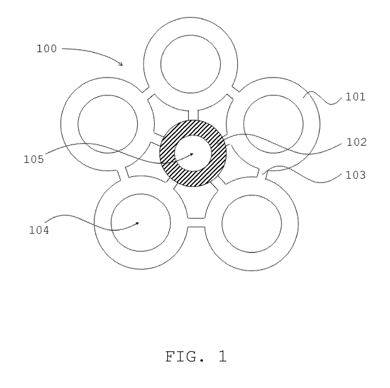
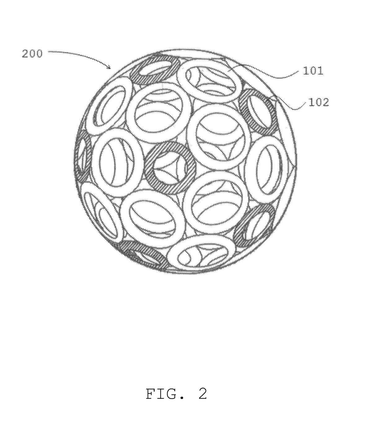
The present invention solves problems related to confinment of particles by using a conductive coil confinement system that uses more conductive coils closer to the shape of a rounded sphere to improve confinment. This configuration creates more cusps and evenly distributes the pressure created by the particles confined within the apparatus. The addition of multiple confining magnetic fields angled off-center towards the same general relative direction promotes a rotational pattern throughout the confined plasma, enhancing confinment and reducing the amount of particles that can escape the system. The rotational movement of particles also allows for more equal distribution of pressure created by confined particles and reduces the amount of pressure acting upon the system because the outward force of the confined particles is reduced. This invention also produces a current from the confined plasma.

Problems solved by technology

To date the creation of a successful fusion device has not yet been developed that has the ability to reach or surpass the break-even point to be deemed as a viable alternate energy source.
Both of these systems have failed in coming close to meeting the break-even point of fusion.

Method used


Image

  • Fusion energy device with geodesic deviation gravitational effects
  • Fusion energy device with geodesic deviation gravitational effects
  • Fusion energy device with geodesic deviation gravitational effects

Examples


Embodiment Construction

[0048]The various embodiments and variations there of illustrated in the accompanying figures and / or described herein are merely exemplary and are not meant to limit the scope of the invention. It is to be appreciated that numerous variations of the invention have been contemplated as would be obvious to one of ordinary skill in the art with the benefit of this disclosure. Rather, the scope and breadth afforded this document should only be limited by the claims provided herein while applying either the plain meaning to each of the terms and phrases in the claims or the meaning clearly and unambiguously provided in the specification.

[0049]The terms and phrases as indicated in parenthesis (“”) in this section are intended to have the meaning ascribed to them in this section applied to them throughout this document including the claims unless clearly indicated otherwise in context.

[0050]The term ‘or’ as used in this specification and the appended claims is not meant to be exclusive rat...


PUM


Abstract

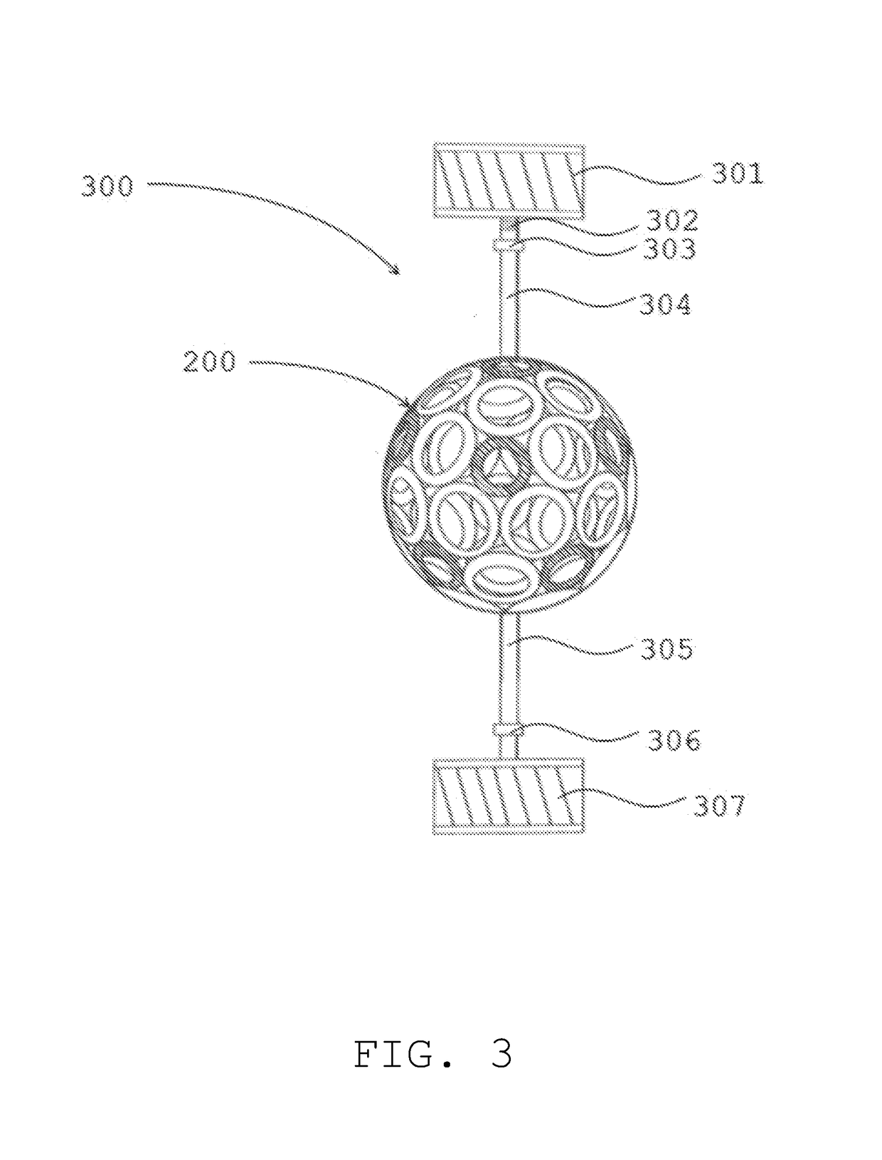
A fusion reactor with a spherical shaped confinement apparatus comprising a plurality of conductive coils that form a rotating negative potential well about a confined center at the center of the system, confining electrons expelled from a surrounding electron discharging grid to obtain a curved spherical rotation pattern to the electrons confined with in the confinement apparatus. The confinement apparatus is also rotated by a multipolar rotating electric machine to promote improved confinement by reducing the amount of time for electrons to escape confinement and shaping the particles in a more curved and spherical shape to allow converging and diverging geodesic effects to enhance tighter and denser particle confinement. This fusion concept reduces the amount of energy needed to operate while minimizing magnetic reconnection disturbances, allowing the NESAR to be the world's first reactor to meet the break-even point of fusion with possible gravitational effects.

Description

CROSS REFERENCE TO RELATED APPLICATIONS[0001]This application claims the benefit under 35 U.S.C. § 119(e) of U.S. Provisional Patent Application Ser. No. 62 / 561,227, filed on Sep. 21, 2017, which Application is incorporated herein in its entirety.TECHNICAL FIELD[0002]This invention is a confinement device that perpetuates fusion reactions with possible gravitational effects by producing a curved circular trajectory upon the particles within the created plasma allowing for much denser plasmas to be confined at a much lower amount of energy needed to confine them relative to other fusion reactors.BACKGROUND[0003]To date the creation of a successful fusion device has not yet been developed that has the ability to reach or surpass the break-even point to be deemed as a viable alternate energy source. As such, many of the physicists that study in the field of plasma physics and fusion technology have directed majority of their efforts in meeting this break-even point for fusion technolog...

Claims


Application Information

Patent Timeline
Patent Type & Authority Applications(United States)
IPC IPC(8): G21B1/05
CPCG21B1/052G21B1/05Y02E30/10G21B1/15G21B1/17H05H1/10
Inventor MOSS, II, SAMUEL PIERRE
Owner MOSS II SAMUEL PIERRE
Learn More