Blast initiation device

a technology of initiation device and initiation tube, which is applied in the direction of blasting, fuses, weapons, etc., can solve the problems of not being able to provide for the uniform transmission of pressure impulse from the firing end of a detonator to all signal transmission lines, and the inability to propagate such impulses. the effect of limiting the range of initiation tube and initiation tub

Inactive Publication Date: 2002-11-07
ORICA EXPLOSIVES TECH PTY LTD
View PDF0 Cites 10 Cited by
  • Summary
  • Abstract
  • Description
  • Claims
  • Application Information

AI Technical Summary

Problems solved by technology

The propagation of such an impulse is therefore limited by the obstacles it encounters along a transmission pathway.
As a result, the positioning of the shock tubes of the detonator assembly of this invention is not spatially uniform and as a result, the shock tubes are not positioned to receive a uniform pressure impulse.
However, this reference does not provide for the uniform transmission of a pressure impulse from the firing end of a detonator to all signal transmission lines held in signal communication therewith.
The spatial relationship of each shock tube with the explosive section of the detonator is the same, and initiation failures are thereby reduced, Although this arrangement is an improvement over the teachings of U.S. Pat. No. 5,703,319, the manufacture of such a detonator assembly is both complicated and expensive.
Consequently, the energy of the explosive composition has to be increased by the use of high brisance compositions such as PETN, which results in the increased production of residual noise and shrapnel.
Despite previous efforts to optimize detonators and detonator assemblies to improve the reliability and safety of blasting practices, limitations in these systems remain prevalent, As a result, there is a continued need for a detonator device which can reliably initiate a plurality of conventional signal transmission lines, under a variety of environmental conditions, while producing minimal amounts of noise and shrapnel,
For example, under the impact of a detonation or pressure imp

Method used


Image

  • Blast initiation device
  • Blast initiation device
  • Blast initiation device

Examples


Embodiment Construction

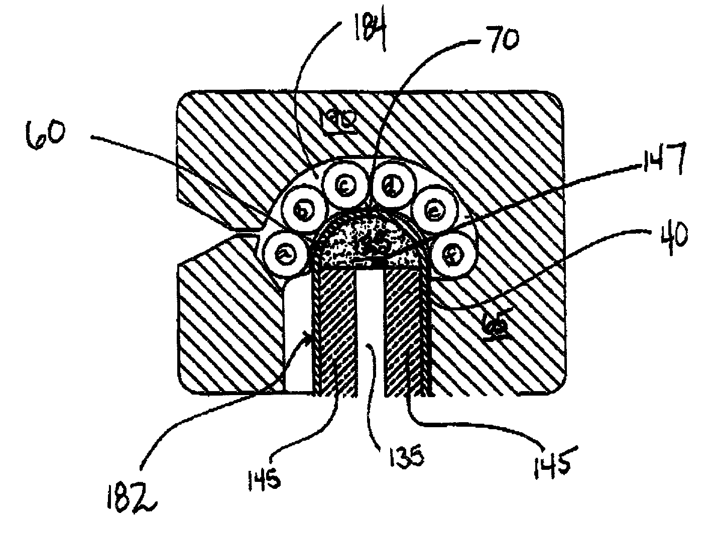
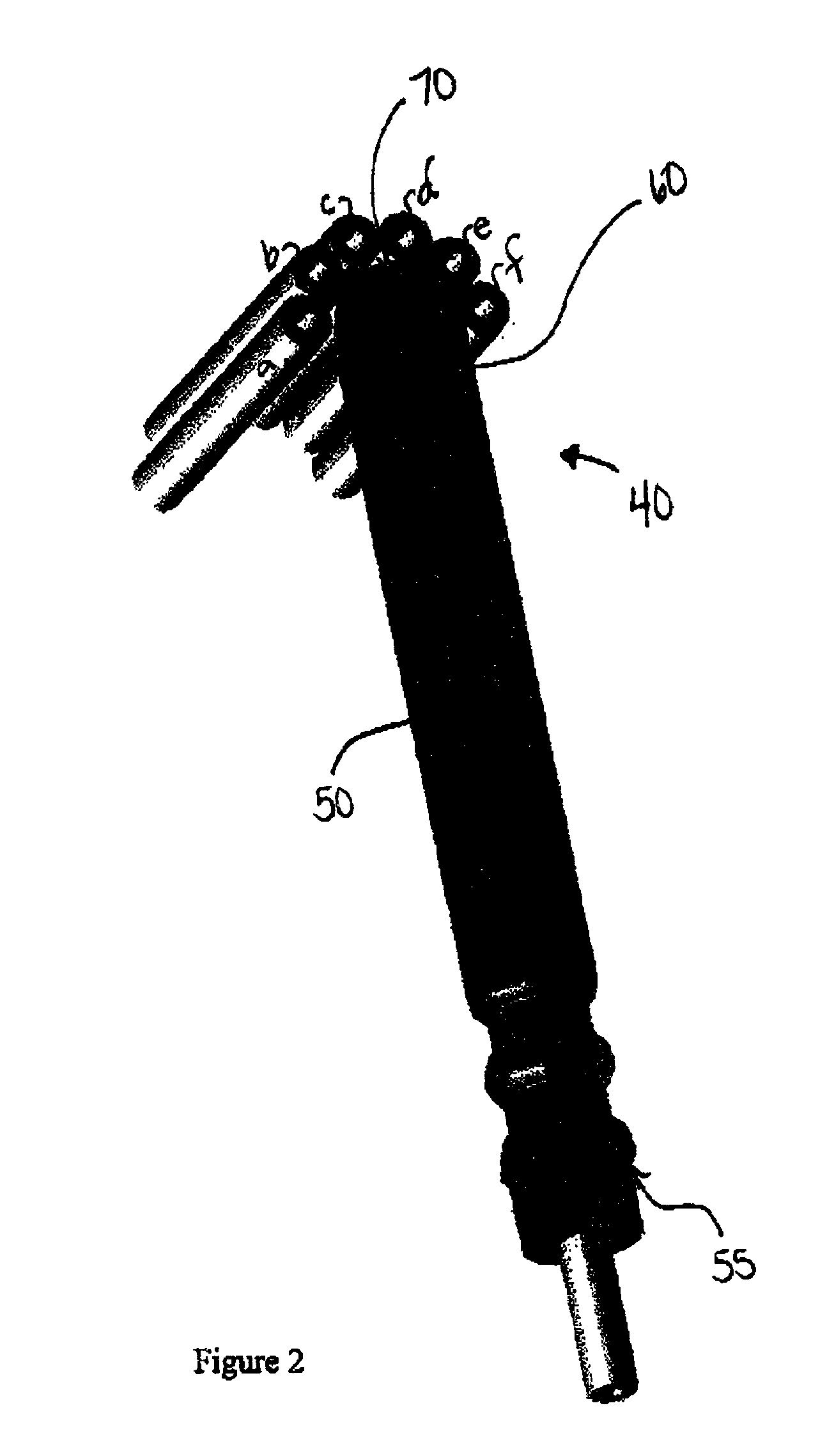
[0131] A comparative initiation test was conducted between round bottom detonators of the present invention and conventional flat end detonators The detonators tested had an outside diameter of 7.5 mm and an inside diameter of 6.65 mm. The round bottom detonators had a closed hemispherical firing end having a diameter uniform with the inside diameter of the detonator body.

[0132] All test detonators were loaded with 200 mg of lead azide as the explosive material and pressed with a flat end punch at a force of 445 Newton. A lead delay element containing a pyrotechnic delay composition of silicon and red lead was inserted on top of the explosive composition and pressed at a force of 1180 Newton, Each test detonator further received an isolation cup, a rubber bushing and a two meter length of input shock tube and subsequently crimped into place

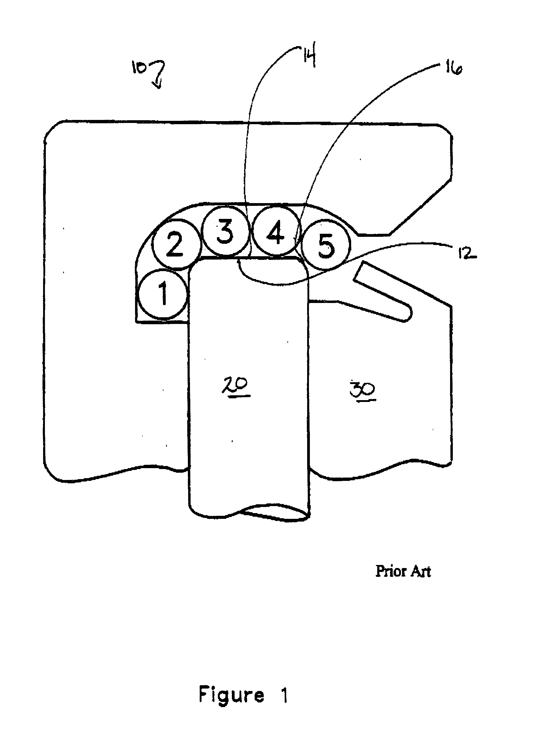
[0133] The test detonators were each mounted into a conventional connector block proximate five output shock tubes. The opposite ends of these ou...


PUM


Abstract

A detonator device and assembly for the initiating a plurality of signal transmission lines with a pressure impulse. The detonator device comprising a detonator casing having a signal receiving end and a firing end. The firing end of the detonator device being substantially shaped to conform with the pressure impulse initiation therein. The firing end having a contact wall of substantially uniform thickness for contacting a plurality of signal transmission lines in a compatible connector element and transmitting a pressure impulse thereto.

Description

[0001] 1. Field of Invention[0002] The present invention relates to blast initiation devices. More specifically, the present invention relates to a detonator device having at least one signal transmission surface for communication of pressure impulse to neighbouring transmission lines or the like, in a detonator assembly or blasting system.[0003] 2. Description of Related Art[0004] Concern about the versatility and precision of blasting systems has been the focus of the explosives industry for decades, Current blasting practices widely employ low brisance transmission lines as a non-electrical means of transmitting blasting signals to target detonators for initiating explosive columns in a precise and reliable manner.[0005] Modern non-electric blasting systems typically comprise a series of shock tubes or signal transmission lines positioned in contact with a donor detonator within a connection block or the like. Transmission lines, or shock tubes as they are more commonly known, ge...

Claims


Application Information

Patent Timeline
IPC IPC(8): C06C7/00F42D1/04
CPCF42D1/043
Inventor CHAN, SEK K.CARRIERE, RAYMONDREID, JOHN T.
Owner ORICA EXPLOSIVES TECH PTY LTD
Why Eureka
Try Eureka