Ultrasonic transducer

a transducer and ultrasonic technology, applied in ultrasonic/sonic/infrasonic diagnostics, instruments, applications, etc., can solve the problems of increasing the cost of producing the ultrasonic transducer, limiting the freedom of design of the ultrasonic transducer, and forming the above-described protective coating involves a relatively high cos

Active Publication Date: 2019-03-28
NIHON DEMPA KOGYO CO LTD
View PDF0 Cites 3 Cited by
  • Summary
  • Abstract
  • Description
  • Claims
  • Application Information

AI Technical Summary

Benefits of technology

[0008]According to an aspect of this disclosure, there is provided an ultrasonic transducer including a piezoelectric element in round shape, an acoustic lens, and an acoustic matching layer. The piezoelectric element generates an ultrasonic sound wave having a wavelength λ. The acoustic lens converges the ultrasonic sound wave. The acoustic matching layer decreases a reflection of the ultrasonic sound wave from a subject. The piezoelectric element has a center having a hole through which an optical fiber that guides a light of a light source

Problems solved by technology

In view of this, a limitation of freedom in designing the ultrasonic transducer has been caused since there is a case where it is not possible to set a thickness of the acoustic matching layer to a desired thin thickness and form th

Method used


Image

  • Ultrasonic transducer
  • Ultrasonic transducer
  • Ultrasonic transducer

Examples


Embodiment Construction

[0015]The following describes embodiments with reference to the drawings. Note that this disclosure is not limited to these embodiments. In addition, the drawings are appropriately scaled, for example, partially enlarged or highlighted to describe the embodiments.

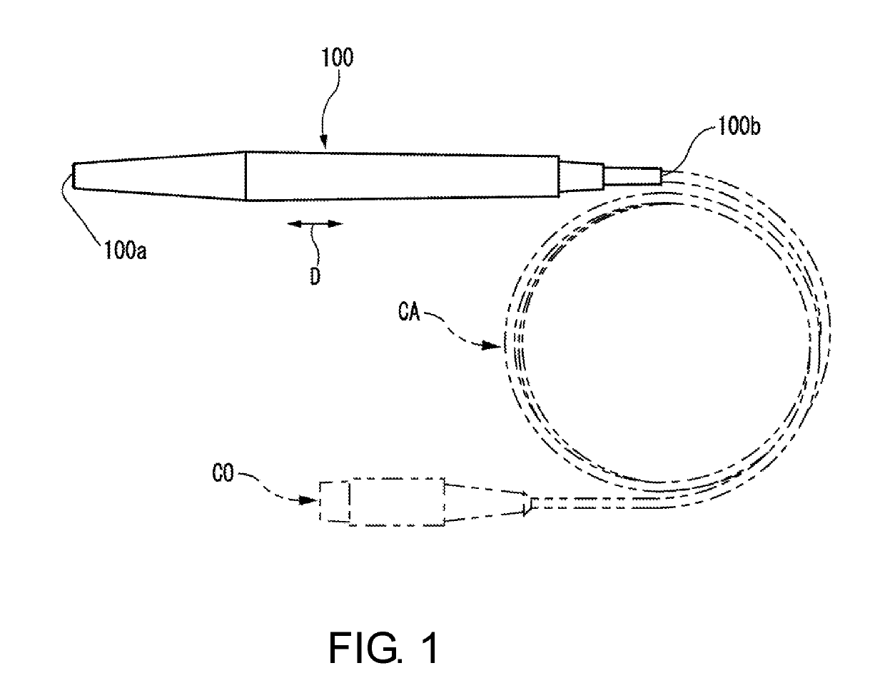
[0016]FIG. 1 is a side view illustrating an exemplary overall configuration of an ultrasonic transducer 100 according to the embodiment. As illustrated in FIG. 1, the ultrasonic transducer 100 is formed into an elongated rod shape.

[0017]The ultrasonic transducer 100 is used as a transmitting / receiving section of an ultrasonic diagnostic device for an ultrasonic sound wave. In this ultrasonic diagnostic device, the ultrasonic transducer 100 is electrically connected to an ultrasonic diagnostic device main body (not illustrated) via a cable CA and a connecting terminal CO. The ultrasonic transducer 100 has a base end portion (the right-side end portion of the ultrasonic transducer 100 in FIG. 1) 100b is connected to the cable...


PUM


Abstract

An ultrasonic transducer includes a piezoelectric element in round shape, an acoustic lens, and an acoustic matching layer. The piezoelectric element generates an ultrasonic sound wave. The acoustic matching layer decreases a reflection of the ultrasonic sound wave from a subject. The piezoelectric element has a center having a hole through which an optical fiber that guides a light of a light source passes. The ultrasonic transducer transmits and receives the ultrasonic sound wave while emitting the light. The acoustic lens has a material using a resin with a withstand voltage, mainly polymethylpentene. The acoustic matching layer has a thickness set to λ/4 by not applying a polyparaxylylene coating for ensuring the withstand voltage on the acoustic matching layer. The optical fiber has a distal end configured not to pass through the acoustic lens. The piezoelectric element and the acoustic matching layer have shapes in a planar surface.

Description

CROSS-REFERENCE TO RELATED APPLICATIONS[0001]This application is based on and claims priority under 35 U.S.C. § 119 to Japanese Patent Application No. 2017-187485, filed on Sep. 28, 2017, the entire content of which is incorporated herein by reference.TECHNICAL FIELD[0002]This disclosure relates to an ultrasonic transducer.DESCRIPTION OF THE RELATED ART[0003]An ultrasonic transducer has been widely used for a transmitting / receiving section of an ultrasonic diagnostic device for an ultrasonic sound wave (for example, see Japanese Unexamined Patent Application Publication No. 2016-025612 and Japanese Unexamined Patent Application Publication No. 2009-247416). There is an ultrasonic transducer that transmits an ultrasonic sound wave while contacting a cornea surface and measures an ocular axial length (a length from a surface of an eye / a cornea to a back of the eye / a retina=a diameter of an eyeball) from a propagation time of the reflected wave. This ultrasonic transducer for measuring...

Claims


Application Information

Patent Timeline
IPC IPC(8): A61B3/10G01N29/24G01N29/28A61B3/00
CPCA61B3/1005G01N29/2437G01N29/28A61B3/0008A61B8/10A61B8/4444A61B8/4494A61B8/4281A61B8/4416A61B8/4483
Inventor KOMIYAMA, KAZUHIKOHASEGAWA, YASUNOBU
Owner NIHON DEMPA KOGYO CO LTD
Why Eureka
Try Eureka