Substrate cleaning method and substrate cleaning apparatus

Active Publication Date: 2019-03-28
SCREEN HLDG CO LTD
View PDF6 Cites 3 Cited by
  • Summary
  • Abstract
  • Description
  • Claims
  • Application Information

AI Technical Summary

Benefits of technology

[0060]Further, in the subsequent residue removal step, a residue removing liquid which has the property of dissolving a solute composition that forms the particle holding layer is supplied to the upper surface of the substrate after the particle holding layer has been removed. It is, thereby, possible to dissolve residues of the particle holding layer and remove them from the upper surface of the substrate.
[0061]Therefore, according to this configuration, the particle holding layer can be peeled from the upper surface of the substrate together with particles held therein to remove the particles at a high removal efficiency. Moreover, it is possible to suppress residues of the particle holding layer from remaining on the upp

Problems solved by technology

However, according to the methods described in both Japanese Patent Application Publication No. 2014-197717 and United States Patent Application Publication No. 2015/128994, since the particle holding

Method used


Image

  • Substrate cleaning method and substrate cleaning apparatus
  • Substrate cleaning method and substrate cleaning apparatus
  • Substrate cleaning method and substrate cleaning apparatus

Examples


Example

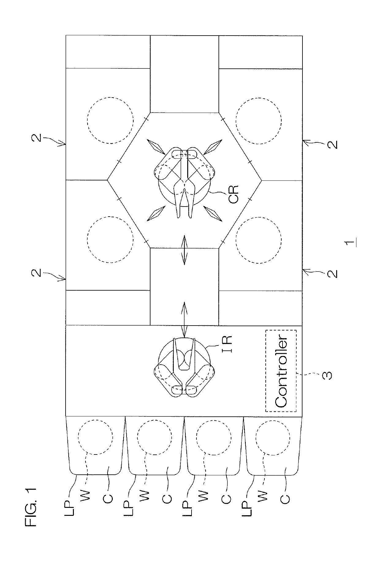
[0076]FIG. 1 is an illustrative plan view which shows a layout of a substrate cleaning apparatus 1 according to the first preferred embodiment of the present invention. The substrate cleaning apparatus 1 is a single substrate processing type apparatus which cleans a substrate W such as a silicon wafer one at a time. In the present preferred embodiment, the substrate W is a disk-shaped substrate.

[0077]The substrate cleaning apparatus 1 includes a plurality of processing units 2 which clean a substrate W, a load port LP at which a carrier C for housing a plurality of substrates W cleaned by the processing units 2 is placed, transfer robots IR and CR which transfer a substrate W between the load port LP and the processing unit 2, and a controller 3 which controls the substrate cleaning apparatus 1.

[0078]The transfer robot IR transfers a substrate W between the carrier C and the transfer robot CR. The transfer robot CR transfers a substrate W between the transfer robot IR and the proces...


PUM


Abstract

A substrate cleaning method includes a processing liquid supplying step which supplies a processing liquid that contains a solute and a volatile solvent to an upper surface of a substrate, a film forming step in which the solvent is at least partially volatilized from the processing liquid supplied to the upper surface of the substrate, by which the processing liquid is solidified or hardened to form a particle holding layer on the upper surface of the substrate, and a removal step in which a peeling liquid for peeling the particle holding layer is supplied to the upper surface of the substrate, thereby peeling and removing the particle holding layer from the upper surface of the substrate. A solute composition that is the solute contained in the particle holding layer has such properties that it is insoluble in the peeling liquid before being heated at a temperature equal to or higher than a quality-changing temperature and it is also changed in quality by being heated at a temperature equal to or higher than the quality-changing temperature and becomes soluble in the peeling liquid. The film forming step includes a heating step in which the processing liquid supplied to the upper surface of the substrate is heated at a temperature less than the quality-changing temperature, thereby forming the particle holding layer on the upper surface of the substrate, with no change in quality of the solute composition. The substrate cleaning method further includes a residue removal step in which a residue removing liquid which has the property of dissolving the solute composition before being heated at a temperature equal to or higher than the quality-changing temperature is supplied to the upper surface of the substrate after the removal step, thereby removing residues that remain on the upper surface of the substrate after the particle holding layer has been removed.

Description

BACKGROUND OF THE INVENTION1. Field of the Invention[0001]The present invention relates to a substrate cleaning method and a substrate cleaning apparatus. Examples of substrates to be processed include semiconductor wafers, substrates for liquid crystal displays, substrates for FEDs (Flat Panel Displays) such as organic electroluminescence displays, substrates for optical disks, substrates for magnetic disks, substrates for magneto-optical disks, substrates for photomasks, ceramic substrates and substrates for solar batteries.2. Description of the Related Art[0002]In a manufacturing process of semiconductor devices, there is executed a cleaning step for removing various types of contaminants attached to a substrate, residues of a processing liquid, a resist, etc., used in a previous step, or various types of particles (hereinafter, collectively referred to as “particles” from time to time).[0003]In the cleaning step, it is generally conducted that a cleaning liquid such as deionized...

Claims


Application Information

Patent Timeline
IPC IPC(8): B08B7/00H01L21/02H01L21/67B08B3/08B08B3/10
CPCB08B2203/007B08B3/08H01L21/02057H01L21/67017B08B7/0014B08B3/10H01L21/67028H01L21/67051H01L21/67103H01L21/68792H01L21/67109H01L21/67248H01L21/6875H01L21/02052H01L21/02343H01L21/324H01L21/6704H01L21/67098
Inventor YOSHIDA, YUKIFUMI
Owner SCREEN HLDG CO LTD
Why Eureka
Try Eureka